Utility accessories and service hardware having luminosity for non-lighted and emergency conditions

a technology of utility accessories and service hardware, which is applied in the direction of luminescence, lighting and heating apparatus, instruments, etc., can solve the problems that none of the prior art patents teach or disclose utility accessories or service hardware having a luminescent outer surfa

Inactive Publication Date: 2003-04-29
PITTS ALGEROME
View PDF6 Cites 5 Cited by
  • Summary
  • Abstract
  • Description
  • Claims
  • Application Information

AI Technical Summary

Benefits of technology

Accordingly, an advantage of the present invention is that it provides for utility accessories, service hardware, electrical fixtures, and houseware devices having luminosity in order to give such items visibility in the absence of any light source for non-lighted and emergency conditions.Another advantage of the present invention is that it provides for a chemiluminescent coating to the outer surface of service hardware and utility accessories in order to illuminate and give them visibility when no visible light is present.Another advantage of the present invention is that it provides for a chemiluminescent coating to such service hardware and utility accessories that include door knobs, door locks, switch plates, electrical receptacle sand the like.Another advantage of the present invention is that it provides for a luminescent outer surface to such aforementioned devices in order to give visible light source to such devices in an interior or exterior area having a minimum or complete absence of light.Another advantage of the present invention is that it provides for a luminescent outer surface having a coating made from luminescent chemical materials selected from the group consisting of white phosphorous, red phosphorous, phosphors, organic guanine (fish scales), metallic and non-metallic micas, bismuth oxychloride, phosphorous oxychloride, or other chemiluminescent materials.Another advantage present invention is that it provides for a luminescent outer surface that produces a light source from a chemiluminescent material which glows white, red, yellow green in the absence of light.Another advantage of the present invention is that it provides for a micro-thin screen cover having a color tint, in which to enhance the luminescent outer surface of such devices in order for the chemiluminescent material coating to be better observed by the user in the absence of any other light source.Another advantage of the present invention is that it provides for a shell protective cover for protecting the luminescent material coating on the outer surfaces of the aforementioned devices from wearing off or deteriorate through normal use and handling.Another advantage of the present invention is that it provides for a luminescent outer surface having a chemiluminescent coating that is long-lasting, durable in use, and reliable for producing a light source in the absence of light.A further advantage of the present invention is that it provides for a chemiluminescent coating on the outer surface of such aforementioned devices where such luminescent material coating may be mass produced in an automated and economical manner on such devices and is readily affordable by the consumer.A latitude of modification, change, and substitution is intended in the foregoing disclosure, and in some instances, some features of the invention will be employed without a corresponding use of other features. Accordingly, it is appropriate that the appended claims be construed broadly and in a matter consistent with the spirit and scope of the invention herein.

Problems solved by technology

None of the prior art patents teach or disclose utility accessories or service hardware having a luminescent outer surface for providing a luminescent (visible) light source in which to locate such devices or hardware in the absence of any type of light source.

Method used


Image

  • Utility accessories and service hardware having luminosity for non-lighted and emergency conditions
  • Utility accessories and service hardware having luminosity for non-lighted and emergency conditions
  • Utility accessories and service hardware having luminosity for non-lighted and emergency conditions

Examples


embodiment 100

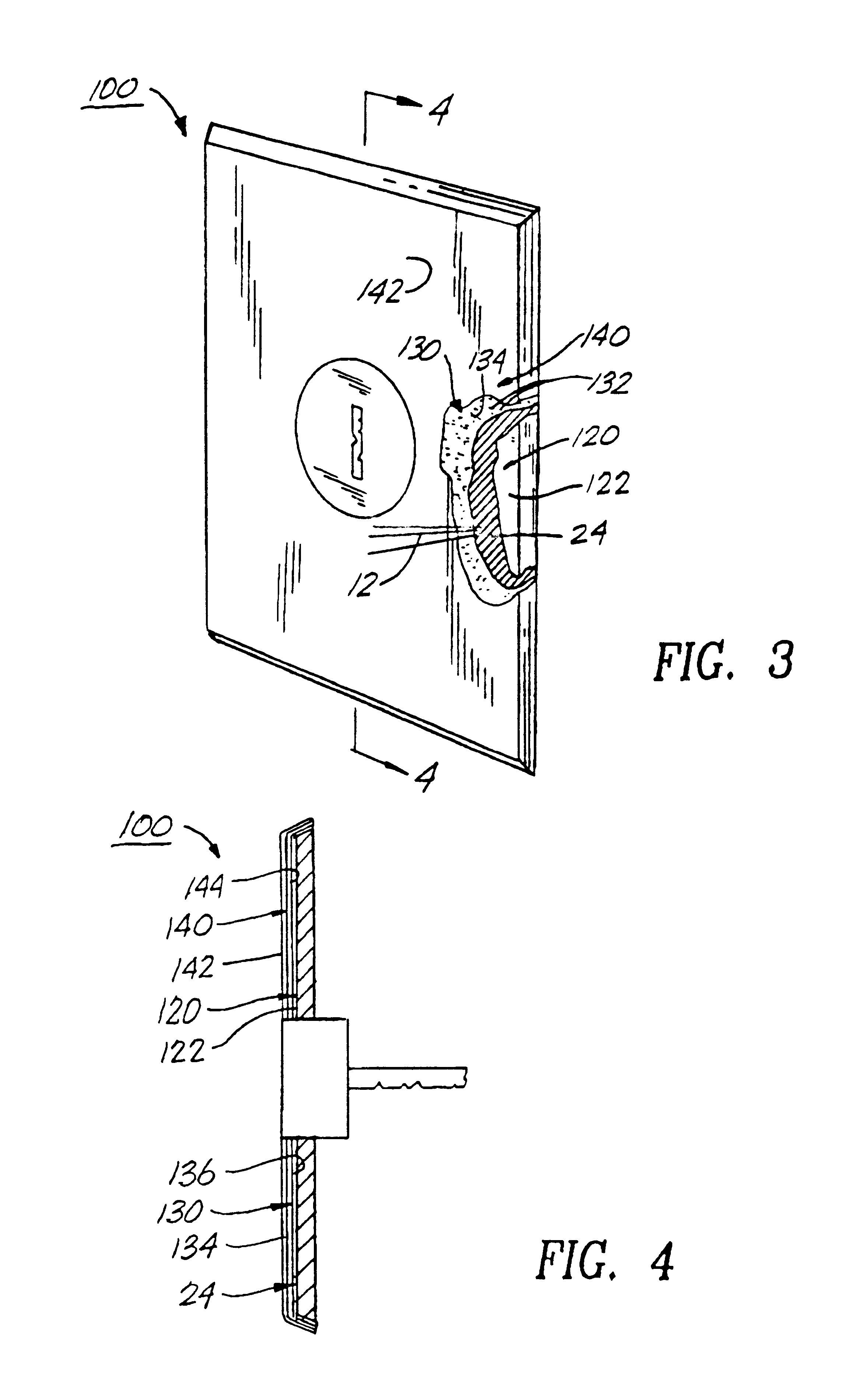
The door lock 100 having luminosity for non-lighted and emergency conditions of the second alternate embodiment of the present invention are represented in detail by FIGS. 3 and 4 of the patent drawings. The door lock 100 includes a chemiluminescent material coating 24 on the outer wall surface 122 of the door lock housing 120, such that the chemiluminescent material coating 24 provides a visible light source 12 in which to locate the door lock 100 in the absence of any light. All aspects of this second alternate embodiment 100 are the same as the first alternate embodiment of the door knob 10, except for the configuration and structure of the door lock 100 (but having the same chemiluminescent material coating 24 thereon).

The switch plate 200 having luminosity for non-lighted and emergency conditions of the third alternate embodiment of the present invention are represented in detail by FIGS. 5 and 6 of the patent drawings. The switch plate 200 includes a chemiluminescent material ...

first alternate embodiment 10

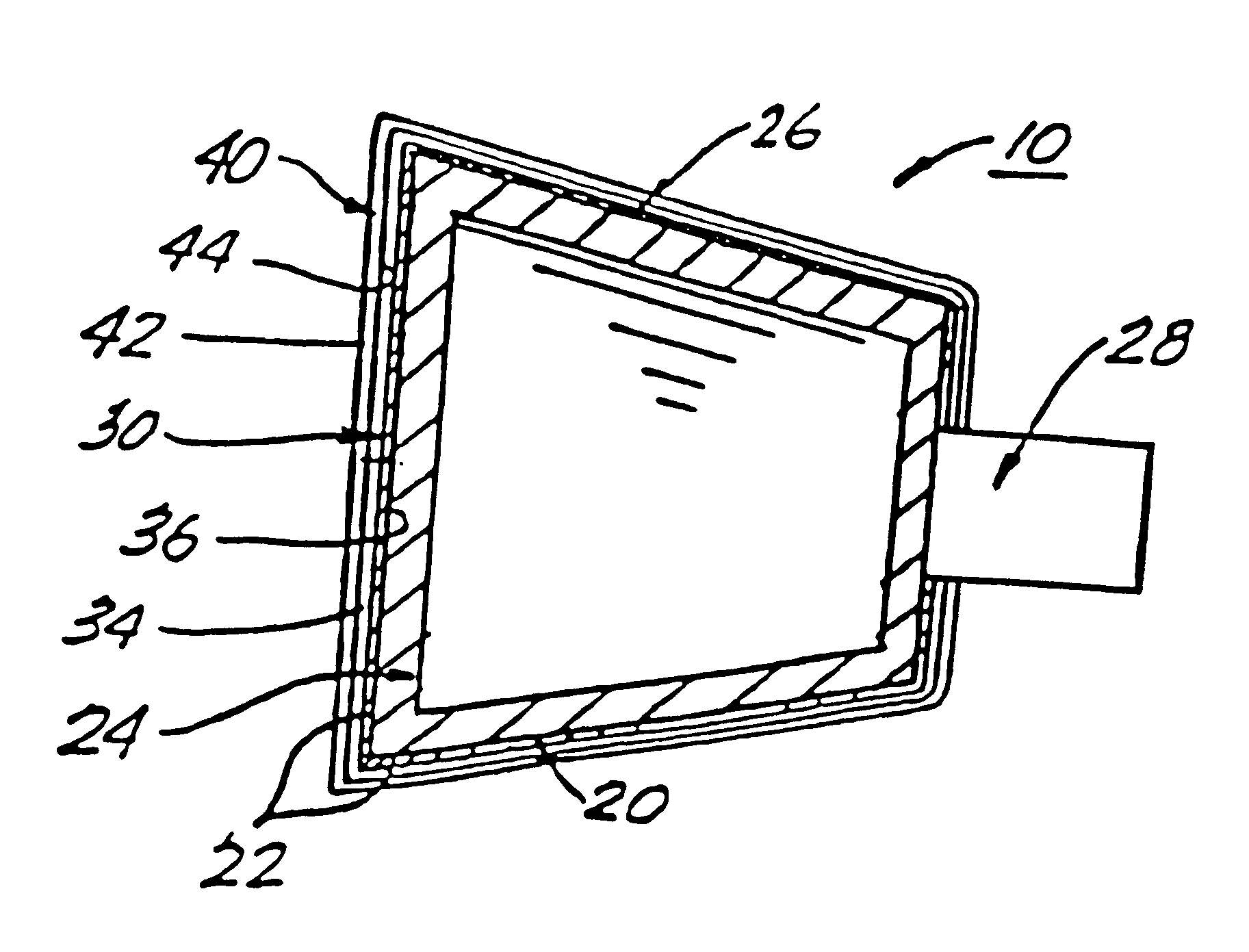
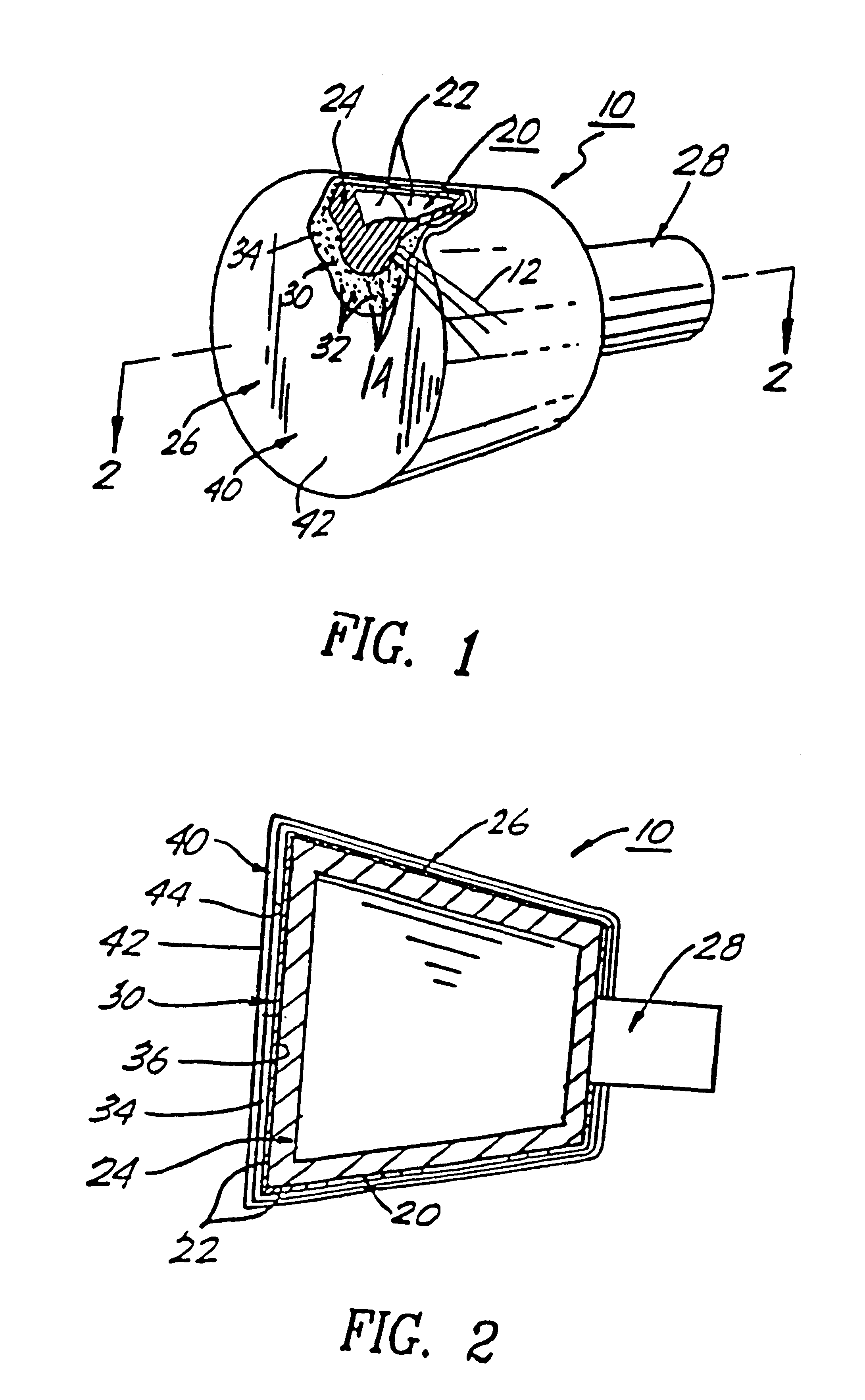
The door knob 10 having luminosity for non-lighted areas and emergency conditions of the first alternate embodiment are depicted in detail by FIGS. 1 and 2 of the patent drawings. The door knob 10 includes a door knob housing 20 having an outer wall surface 22 with a chemiluminescent material coating 24 thereon. The chemiluminescent coating 24 coats the knob section 26 and the neck extension section 28 of the knob housing with a layered thickness in the range of 5 mils to 20 mils of coating.

Door knob 10 also includes a conformed micro-screen cover 30 having a plurality, of micro hole openings 32 therein. Micro-screen cover 30 includes an outer wall surface 34 and an interior wall surface 36. The interior wall surface 36 of the conformed micro-screen cover 30 surrounds the luminescent material coating 24 on the outer wall surfaces 22 of door knob 10. The plurality of micro hole openings 32 allows the chemiluminescent material coating 24 to be better observed by the transfer of oxygen...

second alternate embodiment 100

The door lock 100 having luminosity for non-lighted areas and emergency conditions of the second alternate embodiment are depicted in detail by FIGS. 3 and 4 of the patent drawings. The door lock 100 includes a door lock housing 120 having an outer wall surface 122 with a chemiluminescent material coating 24 thereon. The chemiluminescent coating 24 also coats the lock section member 124 and the key insertion opening 126 of the door lock housing 120 with a layered thickness in the range of 5 mils to 20 mils of coating.

Door lock 100 also includes a conformed micro-screen cover 130 having a plurality of micro hole openings 132 therein. Micro-screen cover 130 includes an outer wall surface 134 and an interior wall surface 136. The interior wall surface 136 of the conformed micro-screen cover 130 surrounds the luminescent material coating 24 on the outer wall surfaces 122 of door lock 100. The plurality of micro hole openings 132 allows the chemiluminescent material coating 24 to be bett...


PUM

PropertyMeasurementUnit
thicknessaaaaaaaaaa
thicknessaaaaaaaaaa
luminosityaaaaaaaaaa

Abstract

A luminescent composite laminate structure for utility accessories and service hardware having luminosity for emergency and non-lighted conditions in which to illuminate the outer surface of such hardware and accessories. The composite laminate structure includes a plurality of layers for the protection of the luminescent outer surface of the laminated hardware or accessories. An outer first layer is a plastic protective covering for resistance to wear and impact; and the outer first layer is covering an inner second layer and has an inner surface wall in contact with the inner second layer. The inner second layer is a plastic micro-thin covering having a plurality of micro-hole openings for the transfer of oxygen (O2) through the micro hole openings in order to increase visibility of the luminescent outer surface; and the inner second layer is covering an inner core third layer and has an inner surface wall in contact with said inner core third layer. The inner core third layer is a luminescent material coating for providing luminosity to the outer surface of such hardware or accessories; and the inner core third layer coats the outer surface of such hardware and accessories.

Description

This invention relates to hardware, electrical fixtures and houseware accessories having luminosity for emergency and non-lighted conditions in which to illuminate the outer surface of such hardware and accessories, and give them visibility in the absence of any light source. More particularly, to luminescent hardware and electrical fixtures such as door knobs, door locks, switch plates, electrical receptacles and the like, in which the chemiluminescent coating on its outer surface gives the user a source of visible light in order for the user to have access to those items in the absence of any light source during emergency conditions.Frequently, many types of emergency conditions and situations are experienced in homes, offices, stores, industrial plant facilities and commercial establishments involving power failures where an interior or exterior area has no visible light. These power failures may be caused by electrical short circuits, fire, accidents, brown-outs, black-outs natu...

Claims


Application Information

Patent Timeline
Patent Type & Authority Patents(United States)
IPC IPC(8): B32B27/06B32B3/10G09F13/20
CPCB32B3/10G09F13/20B32B27/06Y10T428/24331Y10T428/24998Y10T428/249978B32B2307/422B32B2307/412B32B2307/724B32B3/266B32B27/08
Inventor PITTS, ALGEROME
Owner PITTS ALGEROME
Why Eureka
Try Eureka