
Gasket with multiple sealing surfaces

Inactive Publication Date: 2003-01-02
ABB VETCOGRAY
View PDF12 Cites 32 Cited by
  • Summary
  • Abstract
  • Description
  • Claims
  • Application Information

AI Technical Summary

Problems solved by technology

The taper angle of the sealing surface is typically slightly different that the taper angle of the seat, creating an interference metal-to-metal sealing engagement.
However, one version of the seal has a contingent seal leg in the event the conical seat on the lower tubular member is damaged.

Method used


Image

  • Gasket with multiple sealing surfaces
  • Gasket with multiple sealing surfaces
  • Gasket with multiple sealing surfaces

Examples


Embodiment Construction

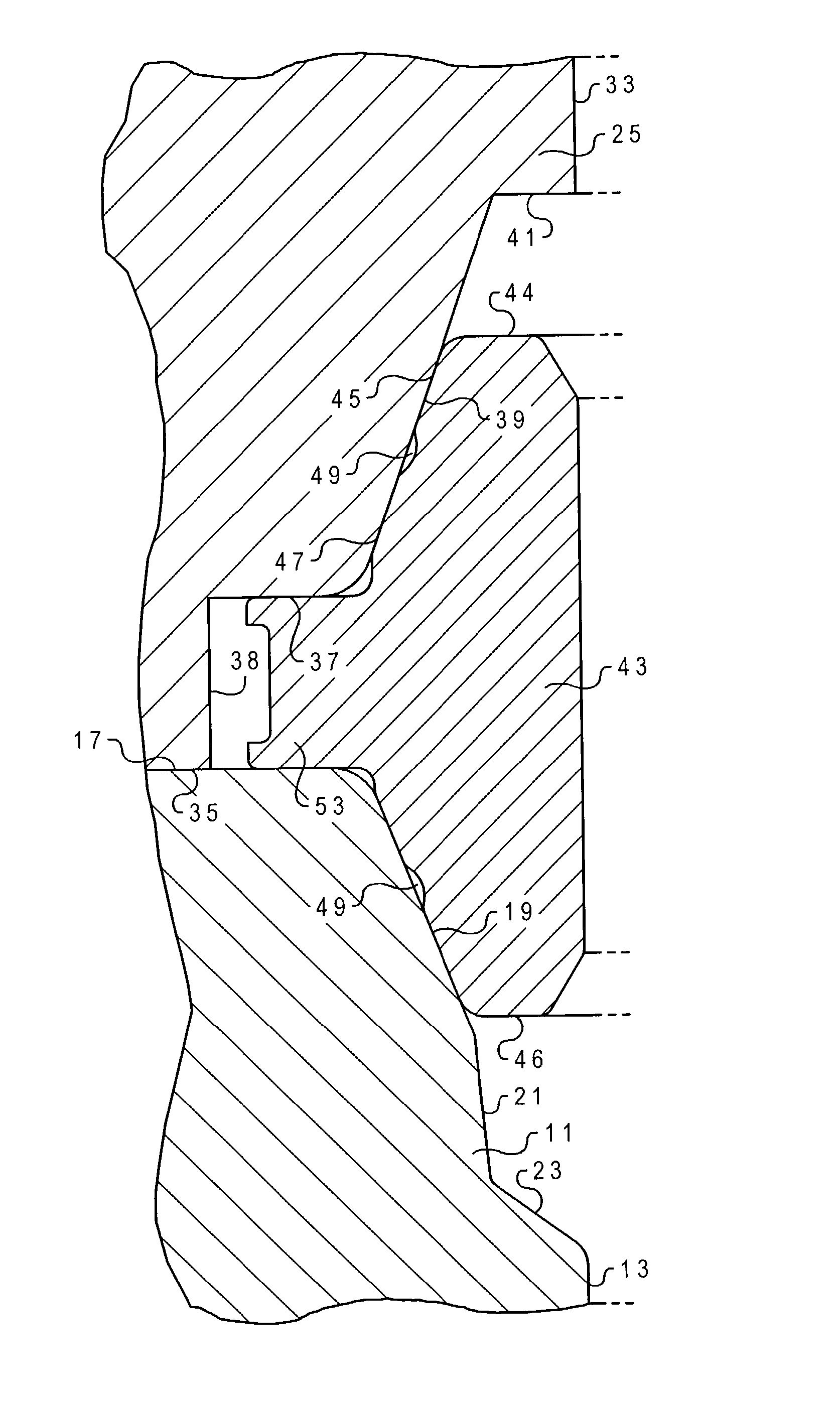
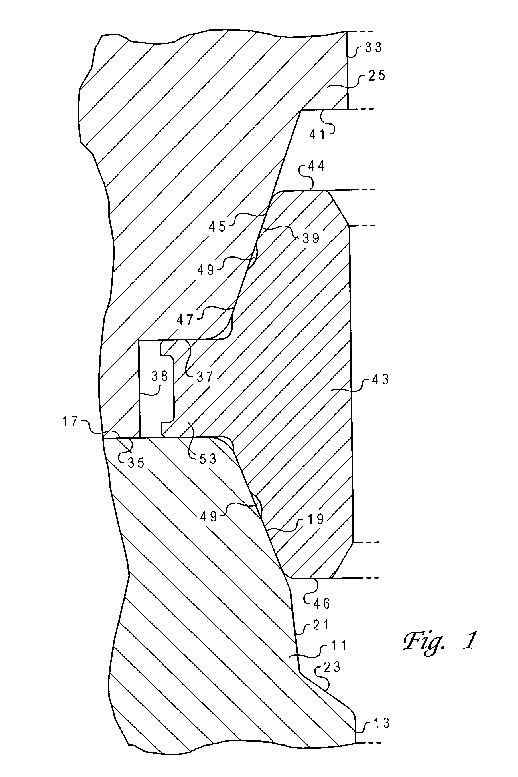
[0012] Referring to FIG. 1, wellhead housing 11 has a bore 13 terminating on its upper end in a rim with an upward facing shoulder 17. A conical primary seat or sealing surface 19 extends downward and inward from shoulderl7. Primary seal surface 19 has a lower marginal edge that joins a secondary seat or seal surface 21. Secondary seal surface 21 is preferably conical, also, but at a lesser angle relative to the axis of bore 13 than primary seal surface 19. The lower marginal edge of secondary seal surface 21 joins a transition surface 23. The axial extent of secondary seal surface 21 is less than the axial extent of primary seal surface 19 in the preferred embodiment. Transition surface 23 is a conical surface with a lower edge that joins bore 13.

[0013] A wellhead connector 25 will connect to wellhead housing 11. Wellhead connector 25 has a lower portion that slides over the exterior of wellhead housing 11. Wellhead connector 25 has a locking member such as dogs (not shown) that ar...


PUM


Abstract

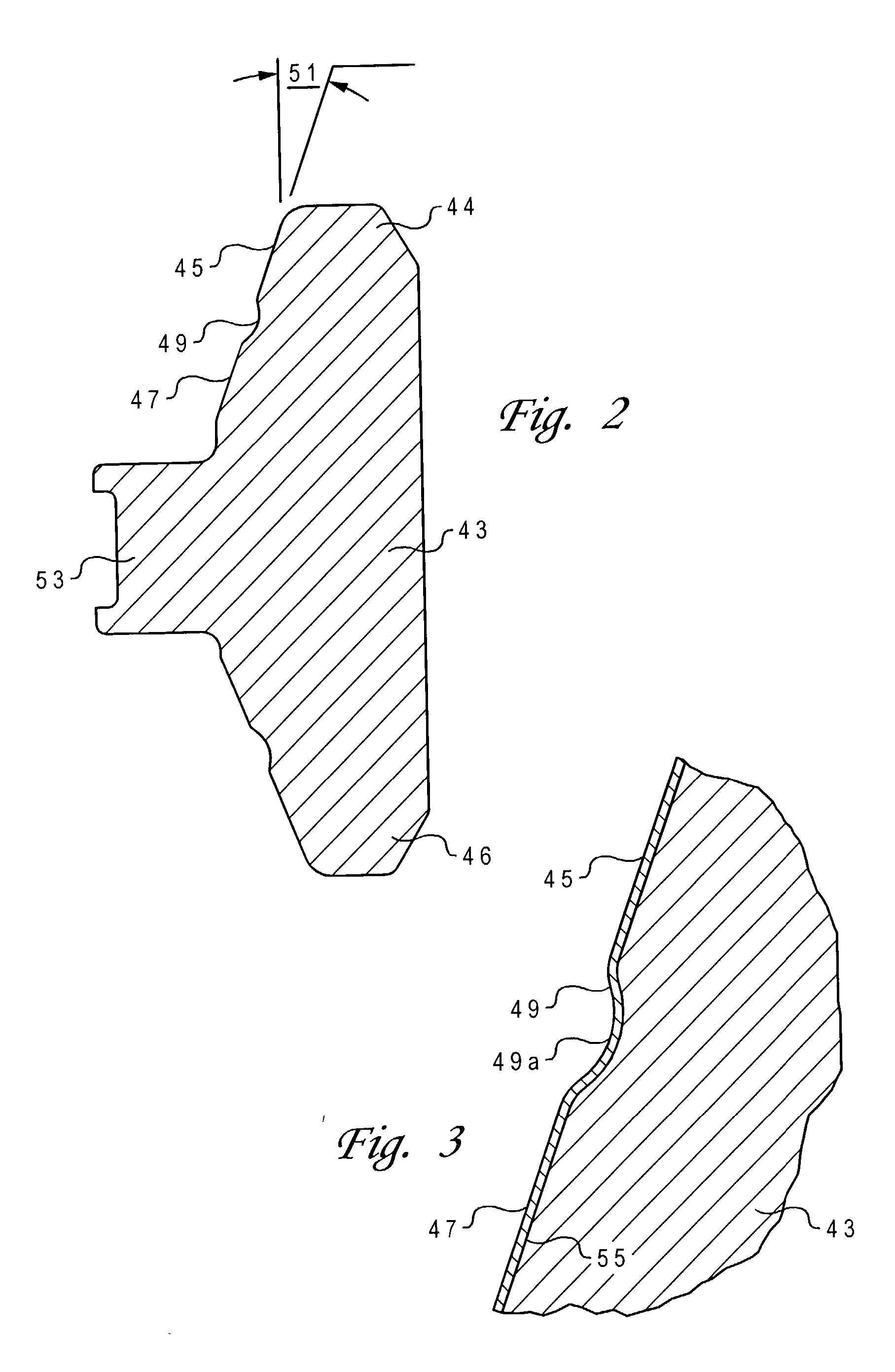
A metal seal for a wellhead assembly has upper and lower legs extending in opposite directions from each other and a rib extending radially outward from a junction of the legs. A first conical band on the upper leg extends uninterrupted from the rib a selected distance toward a tip of the upper leg. A second conical band on the upper leg extends uninterrupted from the tip of the upper leg toward the first conical band. An annular recess is located between the first and second conical bands. The lower leg also has two conical seal bands separated by a recess.

Description

[0001] This application claims priority from the U.S. provisional application Serial No. 60 / 302,162. filed Jun. 29, 2001 entitled "Gasket with Multiple Sealing Surfaces".[0002] The present invention relates in general to metal-to-metal seals, and in particular to an improved gasket for sealing between a wellhead housing and a wellhead connector.DESCRIPTION OF THE PRIOR ART[0003] In oil and gas wellhead assemblies, tubular members are connected end-to-endand sealed by a gasket or seal ring. One type of seal ring, particularly used in subsea wellhead assemblies, is of metal and has upper and lower legs. A rib extends radially outward from a junction of the legs. Each leg has a conical sealing surface that engages a conical seat on one of the wellhead members. The conical sealing surface is a continuous cone that extends from the tip of the leg to the rib. The taper angle of the sealing surface is typically slightly different that the taper angle of the seat, creating an interference m...

Claims


Application Information

Patent Timeline
IPC IPC(8): E21B33/02F16J15/08
CPCF16J15/0887E21B33/02
Inventor SWEENEY, THOMAS F.BRAMMER, NORMANCHALMERS, GEORGE
Owner ABB VETCOGRAY
Learn More