Light-intervention subsea tree system

a technology of light-intervention and subsea trees, which is applied in the directions of survey, sealing/packing, borehole/well accessories, etc., can solve the problem of difficult retrieval

Inactive Publication Date: 2002-06-13
ABB VETCOGRAY
View PDF0 Cites 88 Cited by
  • Summary
  • Abstract
  • Description
  • Claims
  • Application Information

AI Technical Summary

Problems solved by technology

If the valves or choke are in need of service, retrieval is difficult and may require the use of a remotely-operated vehicle.

Method used


Image

  • Light-intervention subsea tree system
  • Light-intervention subsea tree system
  • Light-intervention subsea tree system

Examples


Embodiment Construction

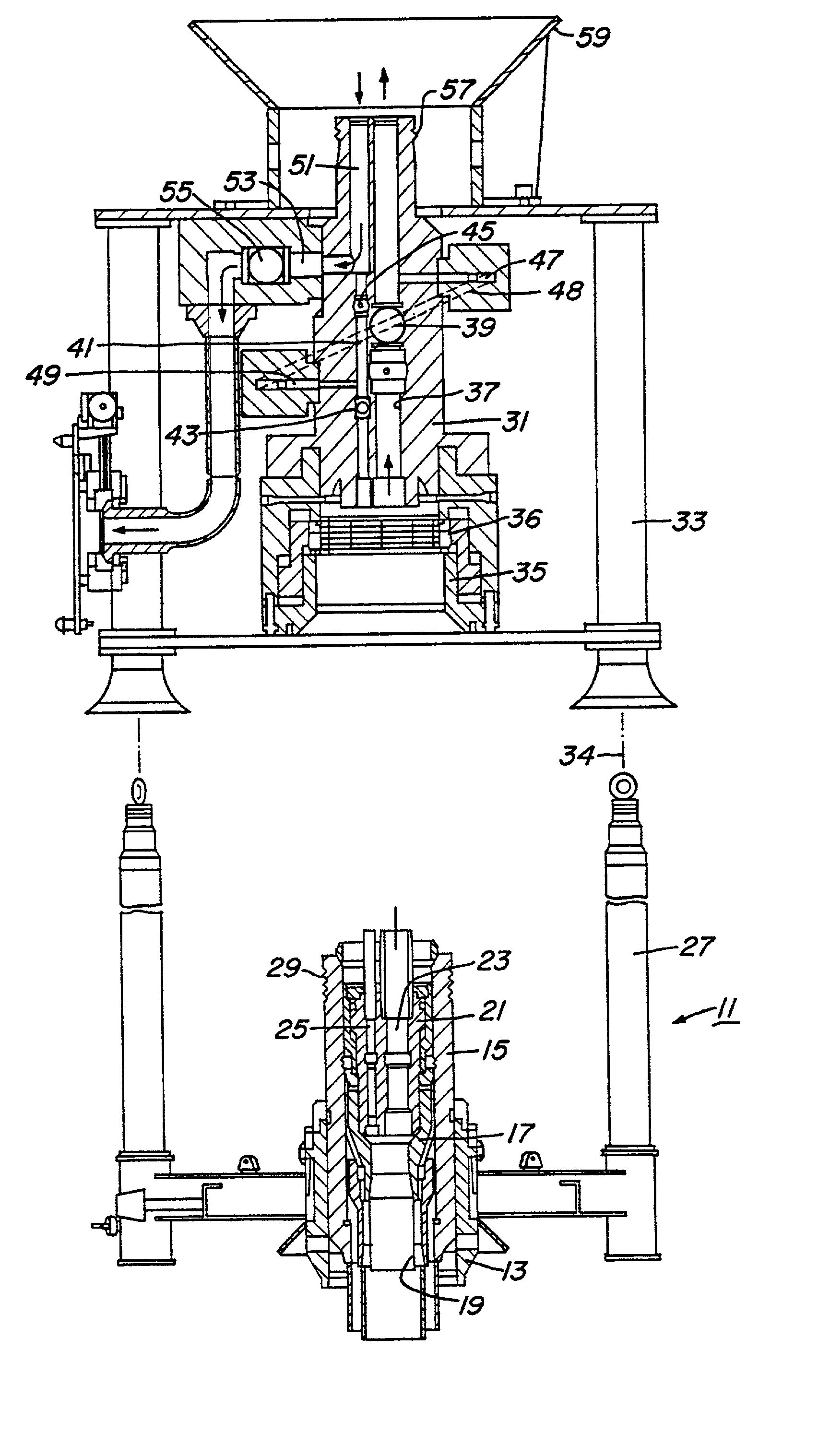
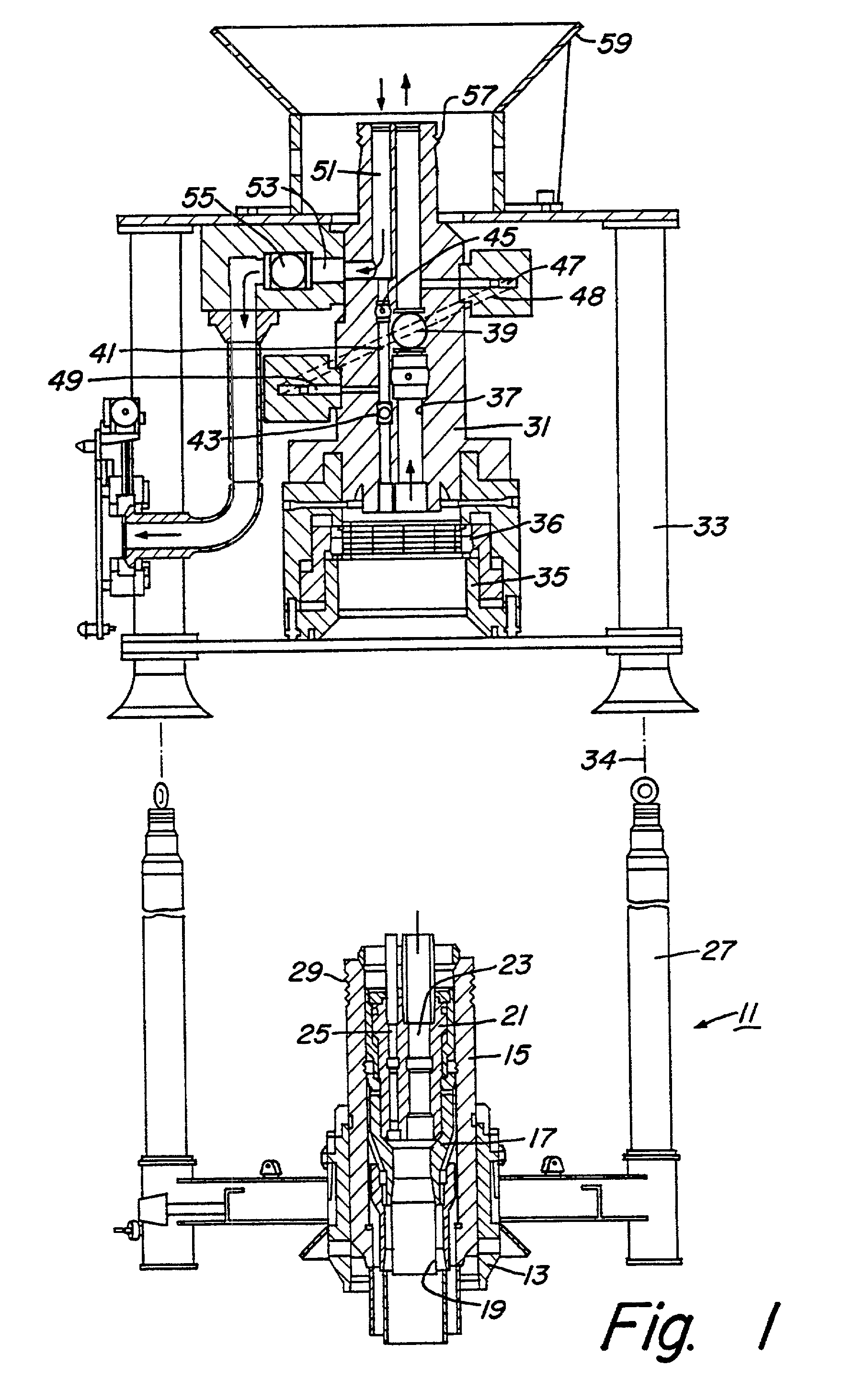
[0011] Referring to FIG. 1, subsea wellhead assembly 11 is conventional. It includes an outer low-pressure wellhead housing 13 that is located at the upper end of a string of a large diameter conductor that extends into the well to a first depth. An inner high-pressure wellhead housing 15 locates within outer wellhead housing 13 and protrudes above. Inner wellhead housing 15 is a tubular member secured to the upper end of large diameter casing that extends to a second depth in the well. The well will have typically two casing hangers 17. The lower one is secured to a string of casing that extends to a third depth in the well. The uppermost casing hanger 17 is secured to production casing 19 that extends to the total depth of the well. Subsea wellhead 11 has four guide posts 27 extending upward. The upper end of inner wellhead housing 15 is a tubular mandrel 29 having an exterior profile with grooves.

[0012] A conventional tubing hanger 21 lands in the bore of inner wellhead housing 1...


PUM


Abstract

A subsea well apparatus has features for controlling and monitoring production fluid flow from a well. A Christmas tree lands on a subsea wellhead, the tree having a tubular, open upper end. A first flow passage extends from a lower end of the tree to the upper end for communicating fluid with the well. A second flow passage extends downward from the upper end of the tree and has an outlet on a sidewall of the tree for communicating with a flowline. A production module lands on and is retrievable from the upper end of the tree, the module having a flow loop with one end in communication with the first flow passage and another end in communication with the second flow passage. At least one flow interface device is located in the loop of the production module. The flow interface device may be used to monitor or control the flow and may be a temperature or pressure sensor, a flow or multi-phase flow meter, or a choke.

Description

[0001] Benefit is herein claimed of the filing date under 35 USC .sctn.119 and / or .sctn.120 and CFR 1.78 to United States Provisional Patent Application Serial No. 60 / 170,061, filed on Dec. 10, 1999, entitled "Light Intervention Subsea Tree System."[0002] 1. Field of the Invention[0003] This invention relates in general to subsea oil and gas production systems and in particular to a subsea tree assembly having certain components that are retrievable by a light-duty workover vessel.[0004] 2. Description of the Prior Art[0005] A conventional subsea wellhead assembly includes a wellhead housing which supports one or more casing hangers located at upper ends of strings of casing extending into the well. A production tree is landed on the wellhead for controlling the production of well fluids. The tree usually carries a choke and valves to control the flow and sensors to monitor the flow.[0006] With both conventional and horizontal trees, external chokes and production valves are used to...

Claims


Application Information

Patent Timeline
Patent Type & Authority Applications(United States)
IPC IPC(8): E21B33/035E21B34/04E21B47/06E21B47/10
CPCE21B33/035E21B33/0355E21B47/10E21B47/06E21B47/065E21B34/04E21B47/07
Inventor FENTON, STEPHEN P.OSBORNE, JOHN H.NORDAUNET, ROLF
Owner ABB VETCOGRAY
Why Eureka
Try Eureka