Natural gas turbine generator

a natural gas turbine and generator technology, applied in the direction of fluid couplings, motor/generator/converter stoppers, dynamo-electric converter control, etc., can solve the problems of large footprint, explosion hazards, and higher voltage levels, so as to reduce the explosion hazards, reduce the effect of carbon bridging between connections and reducing the risk of explosion

Active Publication Date: 2010-03-23
REVOLUTION TURBINE TECH LLC
View PDF22 Cites 89 Cited by
  • Summary
  • Abstract
  • Description
  • Claims
  • Application Information

AI Technical Summary

Benefits of technology

[0010]The various embodiments of the disclosed invention provide an arrangement that prevents arcing between adjacent lead connections, thereby minimizing the explosion hazard and eliminating carbon bridging between connections. Various units have also been made more compact relative to existing designs, to provide more electrical generation capacity within a smaller footprint. For example, the present disclosure may produce a natural gas turbine that produces 500 Watts while occupying only a 250-mm×250-mm plan view footprint. The problem of condensation buildup is also mitigated.
[0012]The turbine generator has a rotor that is motivated by a high pressure fluid such as natural gas that is directed tangentially to impinge on the outer perimeter of the rotor. A design is disclosed wherein the full axial length of the rotor is utilized as the impingement surface, thereby increasing the power imparted to the rotor over a minimum length, thereby maintaining a small overall footprint for the turbine generator.
[0013]The fluid enters the turbine generator via inlet passages and exits the unit via outlet passages. The outlet passages are configured to penetrate the interior of the turbine generator at a substantially horizontal angle and at the bottom of the cavities that house the components of the turbine generator, thus enabling the cavities to drain and reducing build up of condensation within the cavities.
[0022]In another embodiment of the invention, a method of using a natural gas turbine includes selecting a turbine generator that has a plurality of electrical outputs and an interior chamber in fluid communication with an inlet and an outlet. The interior chamber contains a stationary core assembly operatively coupled with at least one magnetic element mounted on a rotor rotatable relative to the stationary core assembly for producing electricity at the plurality of electrical outputs. The rotor in this embodiment has a continuous impingement surface. The core assembly has current-bearing components that include a plurality of windings and being at least partially encapsulated within a dielectric casting that hermetically seals the current-bearing components. The method further entails connecting the plurality of electrical outputs to an electrical load and connecting a gas supply line to the inlet, the gas supply line being in fluid communication with a pressurized gas source, the pressurized gas source including a natural gas composition. A gas return line is connected to the outlet, and a gas flow is enabled from the pressurized gas source to flow through the turbine generator, the gas impinging the continuous impingement surface and causing the rotor to rotate the at least one magnetic element relative to the core assembly and produce electricity at the plurality of electrical outputs. The method may further include operating a switch between the electrical output and the electrical load, the switch being switchable between at least a load position and a no-load position. The switch is repeatedly cycled between the load position and the no-load position according to a periodic cycle to increase the average rotational speed of the rotor.

Problems solved by technology

A challenge with increased power output is the requirement for higher voltage levels.
Devices that rely on the spatial separation of electrical connections to provide electrical isolation between the winding terminations may require a larger footprint to accomplish the required isolation.
Increased potential between electrical connections may result in arcing, creating an explosion hazard.
Even where an explosion does not result, such arcing may lead to a build up of carbon deposits on the exposed connections that may eventually bridge between the connections, causing the unit to short out and incur structural damage.
However, in spatially constrained areas (e.g. off shore drilling platforms), the footprint of such an approach may be prohibitive.
Increased power output generally requires a higher mass flow rate through a given unit, which leads to an increase in the amount of condensate that forms and accumulates in the unit.
Existing units have been known to become flooded with accumulated condensation to the point of becoming inoperable.
Another issue in certain applications, independent of power level, is the effect of corrosive gases.
Another common component indigenous to natural gas wells is water vapor, which is also corrosive and can cause operational problems when condensing out as a liquid.
Where isolation from electrical machinery is desired, such an approach may require an isolation chamber distinct from the compartment housing the electrical machinery, as the use of liquids may be precluded for reasons of electrical isolation.
The need for an isolation chamber will generally add to the required footprint of the generator.

Method used


Image

  • Natural gas turbine generator
  • Natural gas turbine generator
  • Natural gas turbine generator

Examples


Embodiment Construction

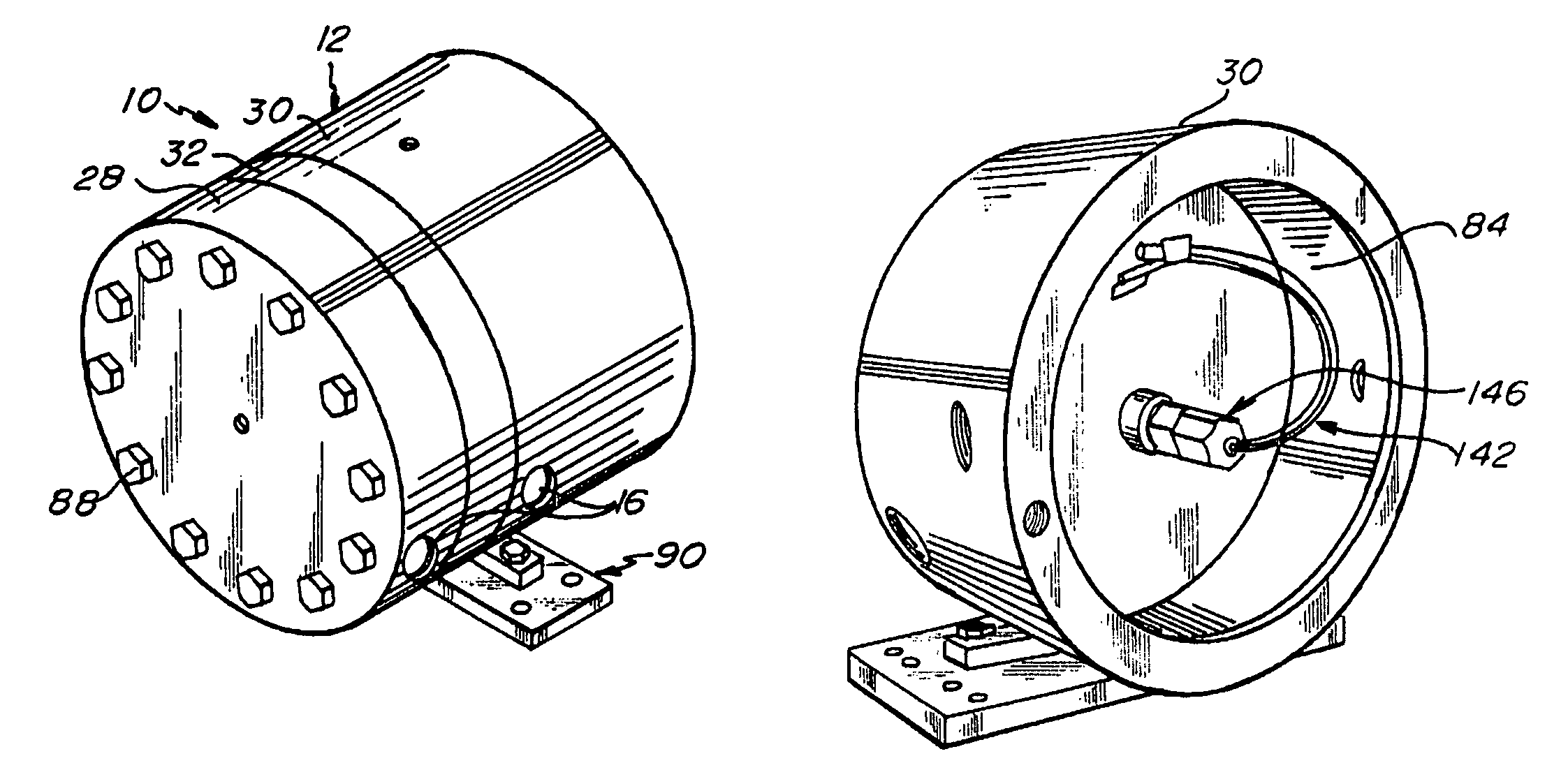
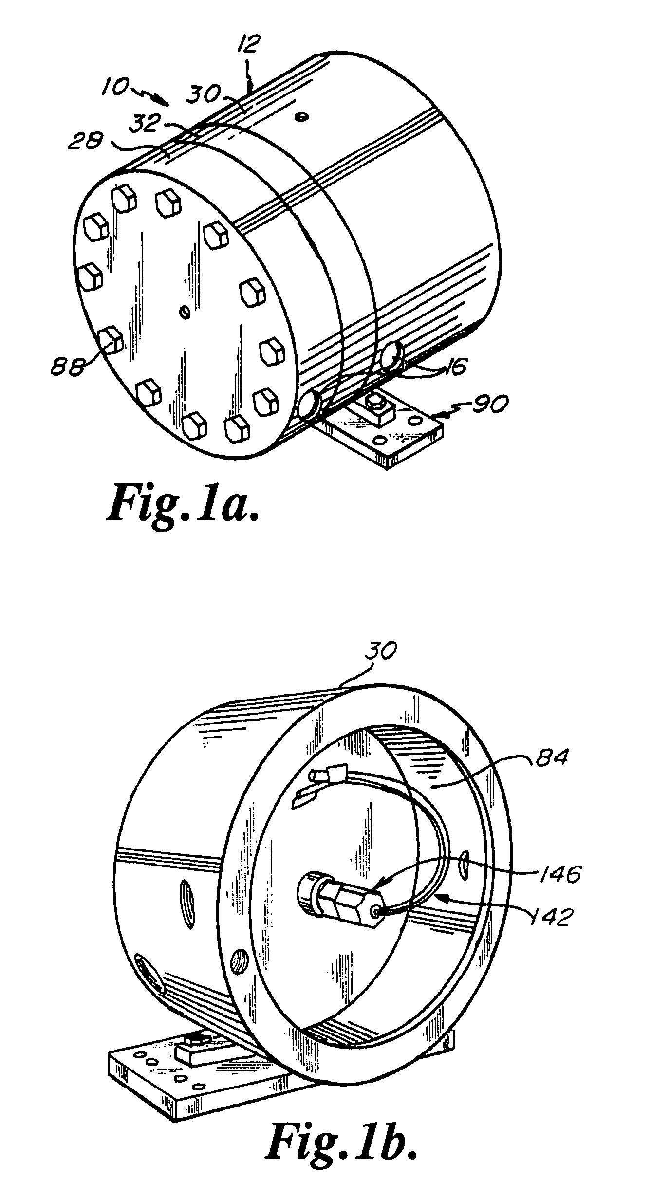
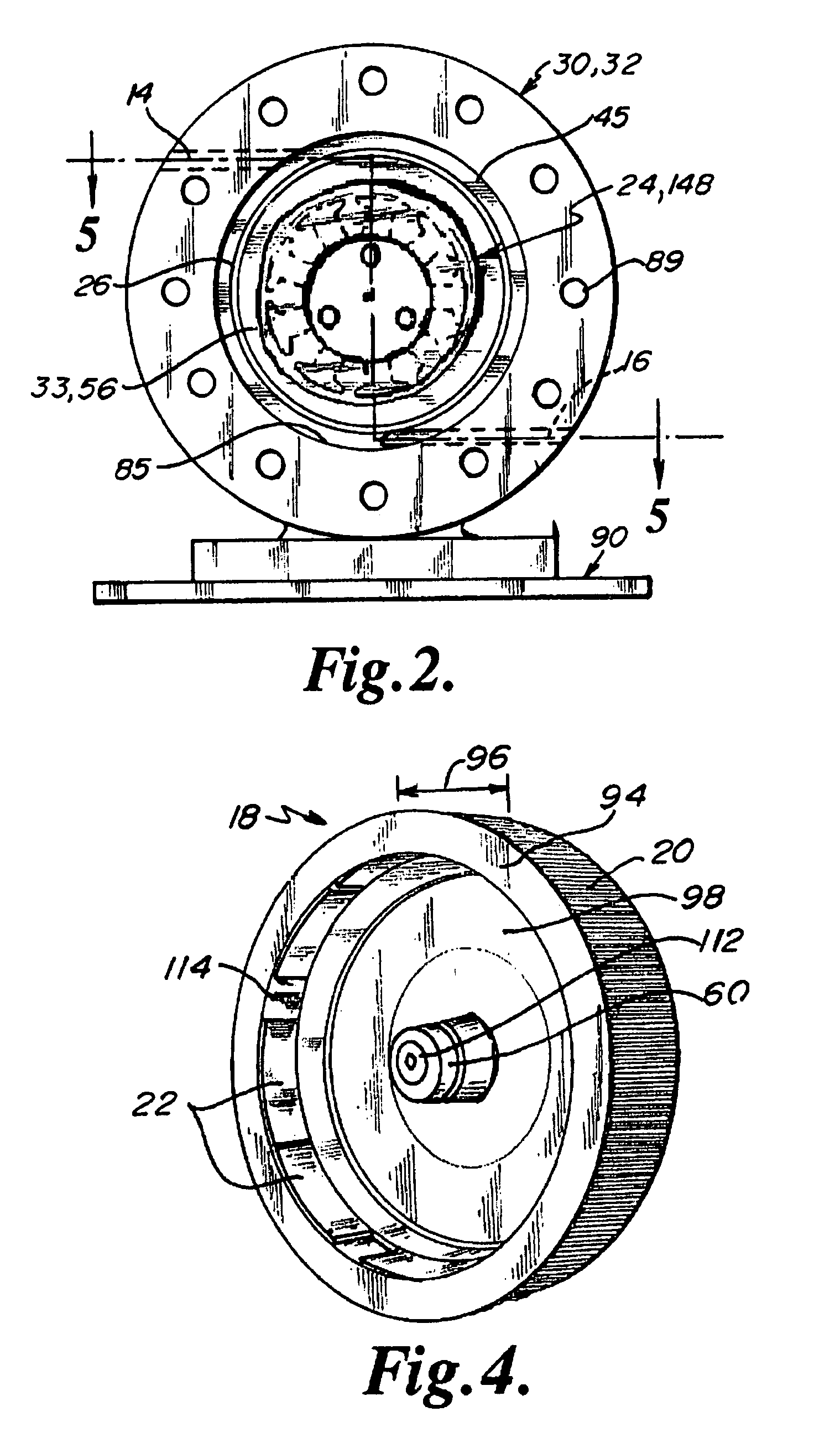
[0047]Referring to the FIGS. 1 through 7, a turbine generator 10 including a housing 12 with an inlet passage 14 and a pair of fluid outlet passages 16 is depicted in an embodiment of the invention. In this embodiment, a rotor 18 having a continuous impingement surface 20 and a magnetic element 22 attached to the rotor 18 is disposed in the housing 12. The rotor 18 may be configured to substantially surround a core assembly 24. The continuous impingement surface 20 may be characterized by a roughened or structured surface such as a saw-tooth profile. A flow restricting device 26 such as a nozzle ring may be fixed in the housing 12 about the rotor 18.

[0048]The housing 12 may include a front housing portion 28 and a back housing portion 30 separated by a spacer ring 32 that combine to form an interior chamber 33 in fluid communication with the inlet passage 14 and the outlet passages 16. The front housing portion 28 includes a flange 34 in which one of the fluid outlet passages 16 may...


PUM


Abstract

A turbine generator utilizing a passive high pressure fluid source such as a natural gas well head. The generator includes a core and lead wires encapsulated in a dielectric medium to isolate current-bearing components from the motivating fluid, thereby preventing carbon bridging and reducing the explosion hazard when the motivating fluid is a hydrocarbon. The turbine generator includes a rotor that utilizes the full length as an impingement surface for imparting momentum to the rotor, thereby maintaining a compact design that reduces the overall footprint of the turbine generator. Fluid exits the generator via horizontal passages that penetrate the lower extremities of the turbine generator, preventing the buildup of condensation in the unit.

Description

RELATED APPLICATIONS[0001]This application claims the benefit of U.S. Patent Application No. 60 / 795,743, filed 27 Apr. 2006, which is hereby incorporated by reference in its entirety.FIELD OF THE INVENTION[0002]The present invention relates to turbines and generators and, more particularly, to turbines with integrated generators.BACKGROUND OF THE INVENTION[0003]Turbine generators that exploit passive pressurized sources such as natural gas well heads have found utility in low power applications (100 watts or less). An example of such a generator is disclosed in U.S. Pat. No. 5,118,961 to Gamel and owned by S&W Holdings, Inc., the assignee of the present patent application. The reliability of these units has resulted in a wider variety of applications by relevant consumers, and attendant demands for higher power output.[0004]A challenge with increased power output is the requirement for higher voltage levels. Devices that rely on the spatial separation of electrical connections to pr...

Claims


Application Information

Patent Timeline
Patent Type & Authority Patents(United States)
IPC IPC(8): F02C3/10
CPCF01D1/34F01D15/10F05D2210/10F05D2210/12F02C1/02F02C7/30H02K3/522H02K5/12H02K7/1823H02P3/00H02P9/04
Inventor SAUCIER, NEIL C.
Owner REVOLUTION TURBINE TECH LLC
Why Eureka
Try Eureka