Miniaturized reverse-fed planar inverted F antenna

a reverse-fed planar and antenna technology, applied in the direction of antennas, antenna details, electrical equipment, etc., can solve the problems of not meeting the present design of the antenna, the product space of the manufacture of wireless devices such as handsets, pda's and laptops is very small,

Inactive Publication Date: 2003-02-06
E TENNA CORP
View PDF4 Cites 73 Cited by
  • Summary
  • Abstract
  • Description
  • Claims
  • Application Information

AI Technical Summary

Benefits of technology

0008] By way of introduction only, the present invention provides in one embodiment a reverse-fed planar inverted F antenna. In another embodiment, the present invention provides a planar inverted F antenna (PIFA) including a radiating element, a feed, and a radio frequency (RF) short positioned between the feed and a radiating portion of the radiating element.

Problems solved by technology

Manufacturers of wireless devices such as handsets, PDA's and laptops have very little room in their products given these extreme size and cost pressures.
Such wireless devices typically pack a substantial amount of circuitry in a very small package.
To date, however, none of these antennas satisfy the present design goals, which specify efficient, compact, low profile antennas whose height is at most .lambda. / 60 above a ground plane, where A is the resonant frequency.

Method used


Image

  • Miniaturized reverse-fed planar inverted F antenna
  • Miniaturized reverse-fed planar inverted F antenna
  • Miniaturized reverse-fed planar inverted F antenna

Examples


Embodiment Construction

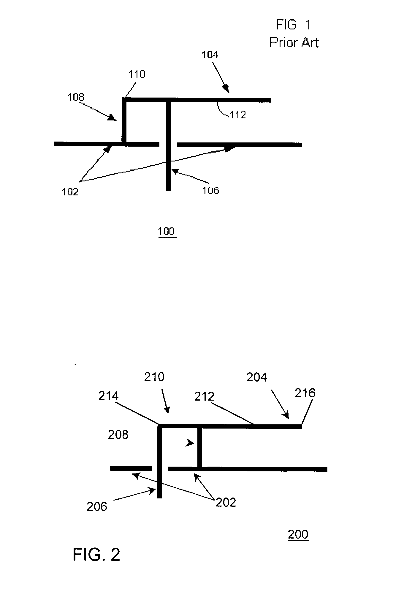
[0022] Referring now to the drawing, FIG. 1 is a diagram showing a cross sectional view of a conventional planar inverted-F antenna (PIFA) 100. The PIFA 100 includes a ground plane 102 and a radiating element 104. The conventional PIFA 100 is defined with a feed 106 positioned between a shorted end 110 and a radiating portion 112 of the radiating element 104. A radio frequency (RF) short 108 electrically shorts the shorted end 110 of the radiating element 104 to the ground plane.

[0023] The embodiment of the conventional PIFA 100 shows the basic elements of the device. The feed engages the radiating element at a feed point which is offset from the RF ground of the radiating element 104. However, in the conventional device, the feed point is positioned between the RF ground, which engages the radiating element at the shorted end 110 of the radiating element 104.

[0024] FIG. 2 shows a cross sectional view of a reverse-fed planar inverted F antenna (RFPIFA) 200. The RFPIFA includes a gro...


PUM


Abstract

In a planar inverted F antenna (PIFA), the feed and RF grounding connections are reversed yielding improved performance. Relative positioning of these connections is selected to tailor the characteristics of the antenna, such as resonant frequency and impedance bandwidth.

Description

[0001] This application claims priority of U.S. provisional patent application serial No. 60 / 354,697, filed Feb. 4, 2002, and U.S. provisional patent application serial No. 60 / 352,113, filed Jan. 23, 2002, which applications are incorporated herein by reference in its entirety.[0002] This application is related to U.S. Provisional Patent Application serial No. 60 / 310,655 filed Aug. 6, 2001 in the names of William E. McKinzie III, Greg S. Mendolia and Rodolfo E. Diaz and entitled "LOW FREQUENCY ENHANCED FREQUENCY SELECTIVE SURFACE TECHNOLOGY AND APPLICATIONS," which application is incorporated herein by reference in its entirety.[0003] The present invention relates generally to antennas. More particularly, the present invention relates to a reverse-fed planar inverted F-type antenna (PIFA).[0004] Each generation of communication devices is designed to be physically smaller than the previous generation. Small size is desirable to reduce physical size and weight and enhance user conven...

Claims


Application Information

Patent Timeline
Patent Type & Authority Applications(United States)
IPC IPC(8): H01Q5/00H01Q5/357H01Q9/04H01Q15/00
CPCH01Q9/0421H01Q5/357H01Q15/0006
Inventor MENDOLIA, GREG S.DUTTON, JOHNMCKINZIE, WILLIAM E. III
Owner E TENNA CORP
Why Eureka
Try Eureka