Washing machine and its washing method

a washing machine and washing method technology, applied in other washing machines, clutches, textiles and paper, etc., can solve problems such as damage to cloths

Inactive Publication Date: 2003-02-20
SAMSUNG ELECTRONICS CO LTD
View PDF0 Cites 29 Cited by
  • Summary
  • Abstract
  • Description
  • Claims
  • Application Information

AI Technical Summary

Problems solved by technology

However, there is a problem in the washing machine thus constructed according to the prior art in that the drum 18 is braked not to rotate to both directions by operations of the unidirectional brake band 44 and unidirectional clutch bearing 46 and the washing axle line is rotated while power with the spin-dry axle line is disconnected by unwinding operation of the clutch spring 30, such that the pulsator 28 is rotated forward and backward while the spin-dry tub 24 is not rotated during the washing course to thereby prevent from making more than one kind of water current.
There is another problem in that the water current made by the pulsator 28 which is relatively strong cannot adequately cope with a variety of cloths, thereby damaging the cloths.

Method used


Image

  • Washing machine and its washing method
  • Washing machine and its washing method
  • Washing machine and its washing method

Examples


Embodiment Construction

[0046] Preferred embodiments regarding clutch structure of a washing machine and washing control method according to the clutch structure of the present invention will now be described in detail with reference to the accompanying drawings.

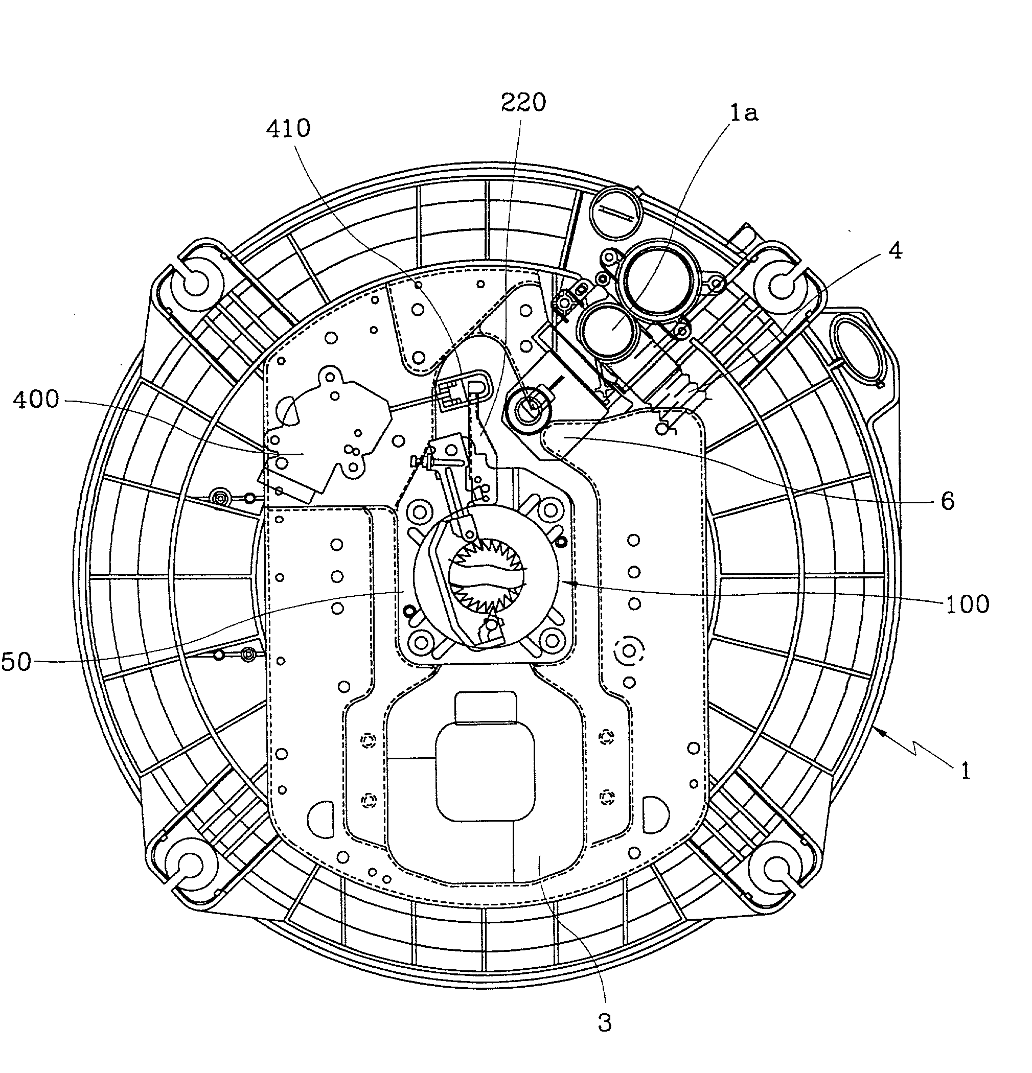
[0047] As illustrated in FIG. 3, the washing machine according to the present invention is constituted by a driving motor 3 disposed at a bottom external side of a water tub 1 and power transmission means 100 centrally formed at a side of the bottom.

[0048] The power transmission means 100 is constituted at a predetermined location distanced therefrom by a drainage hole 1a connected to a drainage hose 4 for draining water in the water tub 1 and a drainage motor 6 for opening and closing the drainage hole 1a. The power transmission means 100 is further constituted by a power switching motor 400 for controlling the power transmission means 100 at two stages via a connecting bracket 410.

[0049] The power transmission means 100 includes, as illustrated i...


PUM


Abstract

A washing machine adopting a clutch structure wherein a power switching motor for controlling a brake band and a clutch lever in multi-stage is separately applied from a drainage motor, such that various kinds of water currents can be embodied according to the multi-control of the power switching motor and a washing method adequate to needs of cloth protection and coping with varying cloths can be provided to thereby enable to protect damage of cloths in advance, the washing machine comprising: a spin-dry tub rotably disposed in a water tub and connected to a dram and a gear case via a power line; a pulsator rotably disposed in a spin-dry tub and connected to a driving shaft coupling and a driving shaft via power line; a brake band for braking and releasing the rotation of the drum; a clutch spring for disconnecting and connecting the power of the driving shaft coupling and the gear case; and power switching motor for controlling in multi-stage operations of clutch sprig and the brake band, the washing method comprising: a first water current control method therein pulsator only rotates in forward / backward direction; a second water current control method wherein a spin-dry tub repeats forward / backward netations is opposition to those of the pulsator; a third water current control method wherein the pulsator and the spin-dry tub rotates in forward direction only; and a fourth water current control method wherein the second water current control is alternatively operated under the third water current control state.

Description

CLAIM OF PRIORITY[0001] This application makes reference to, incorporates the same herein, and claims all benefits accruing under 35 U.S.C. .sctn.119 from my application WASHING MACHINE AND THE WASHING CONTROL METHOD filed with the Korean Industrial Property Office on Sep. 19, 2000 and there duly assigned Serial No. 54981 / 2000.[0002] 1. Field of the Invention[0003] The present invention relates to a fully automated washing machine, and more particularly to a washing machine and its washing method adapted to form a variety of water current according to power multi-switched by a power switching motor operated is separation from a drainage motor, thereby embodying a new washing method appropriate to cloths.[0004] 2. Description of the Prior Art[0005] A water tub 1 according to the prior art includes, as illustrated in FIG. 1, a driving motor 3 formed at a bottom external side thereof for generating a driving force, and power transmission means 2 centrally formed at a bottom surface, a ...

Claims


Application Information

Patent Timeline
Patent Type & Authority Applications(United States)
IPC IPC(8): D06F33/02D06F37/40F16D11/12
CPCD06F37/40F16D11/12
Inventor LEE, JOON-YEOPLEE, KI-SU
Owner SAMSUNG ELECTRONICS CO LTD
Why Eureka
Try Eureka