Image fusing unit of liquid electrophotographic printer

a liquid electrophotographic printer and fusing unit technology, applied in the direction of electrographic process equipment, instruments, optics, etc., can solve the problems of image damage, low heat drying work efficiency,

Inactive Publication Date: 2003-02-20
S PRINTING SOLUTION CO LTD
View PDF0 Cites 5 Cited by
  • Summary
  • Abstract
  • Description
  • Claims
  • Application Information

AI Technical Summary

Problems solved by technology

However, since the image transferred onto the print paper includes a large amount of solvent, an image fusing unit is needed to dry the image after transfer and completely fuse it on the print paper.
However, in the image fusing unit having the above structure, since the drying portion 1 is configured in a non-contact heating manner, the efficiency of heat in the drying work is low.
In this case, however, since an image which is not sufficiently dried needs to be contacted, the image may be damaged during a drying step.

Method used


Image

  • Image fusing unit of liquid electrophotographic printer
  • Image fusing unit of liquid electrophotographic printer

Examples


Embodiment Construction

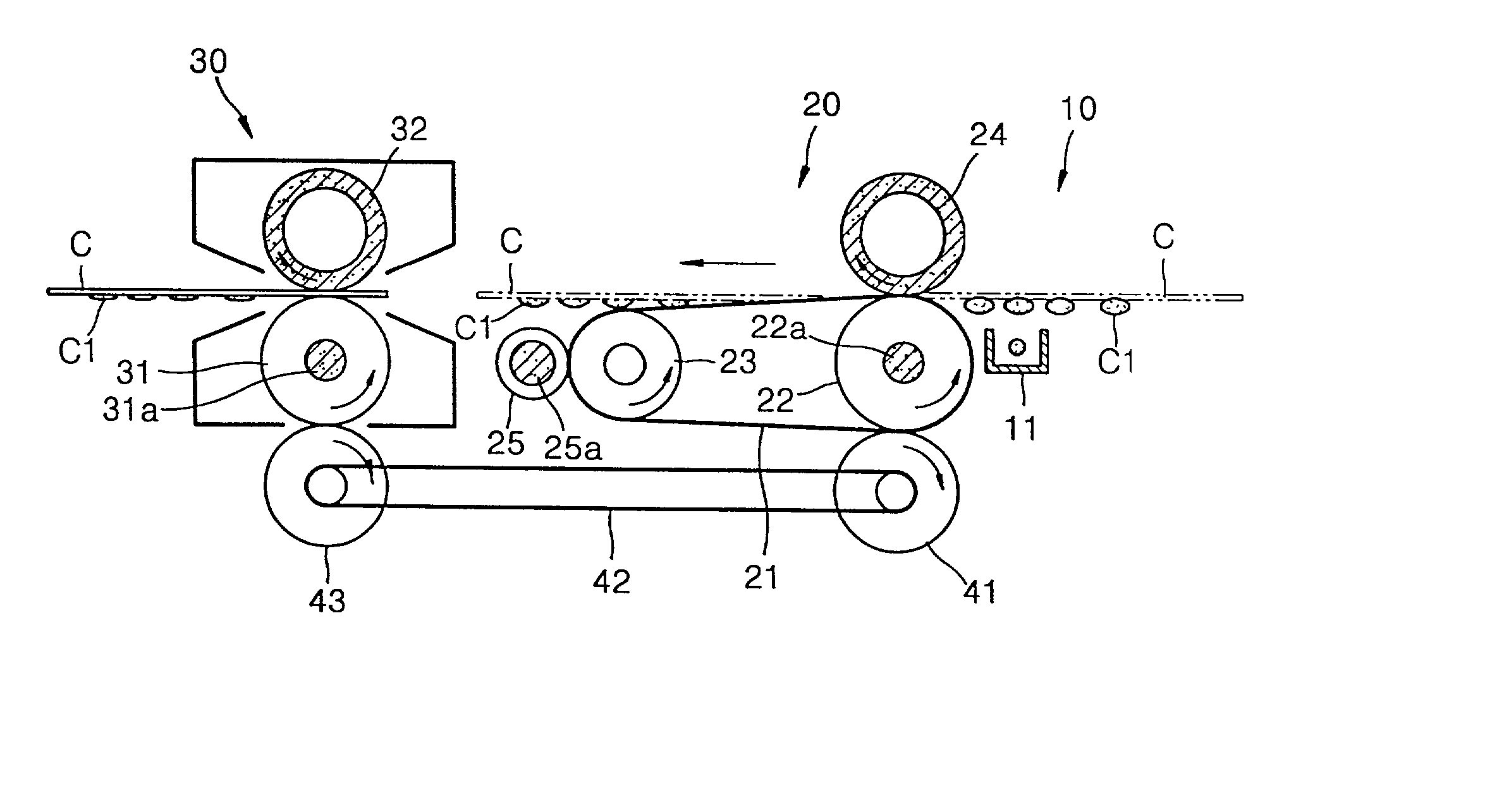
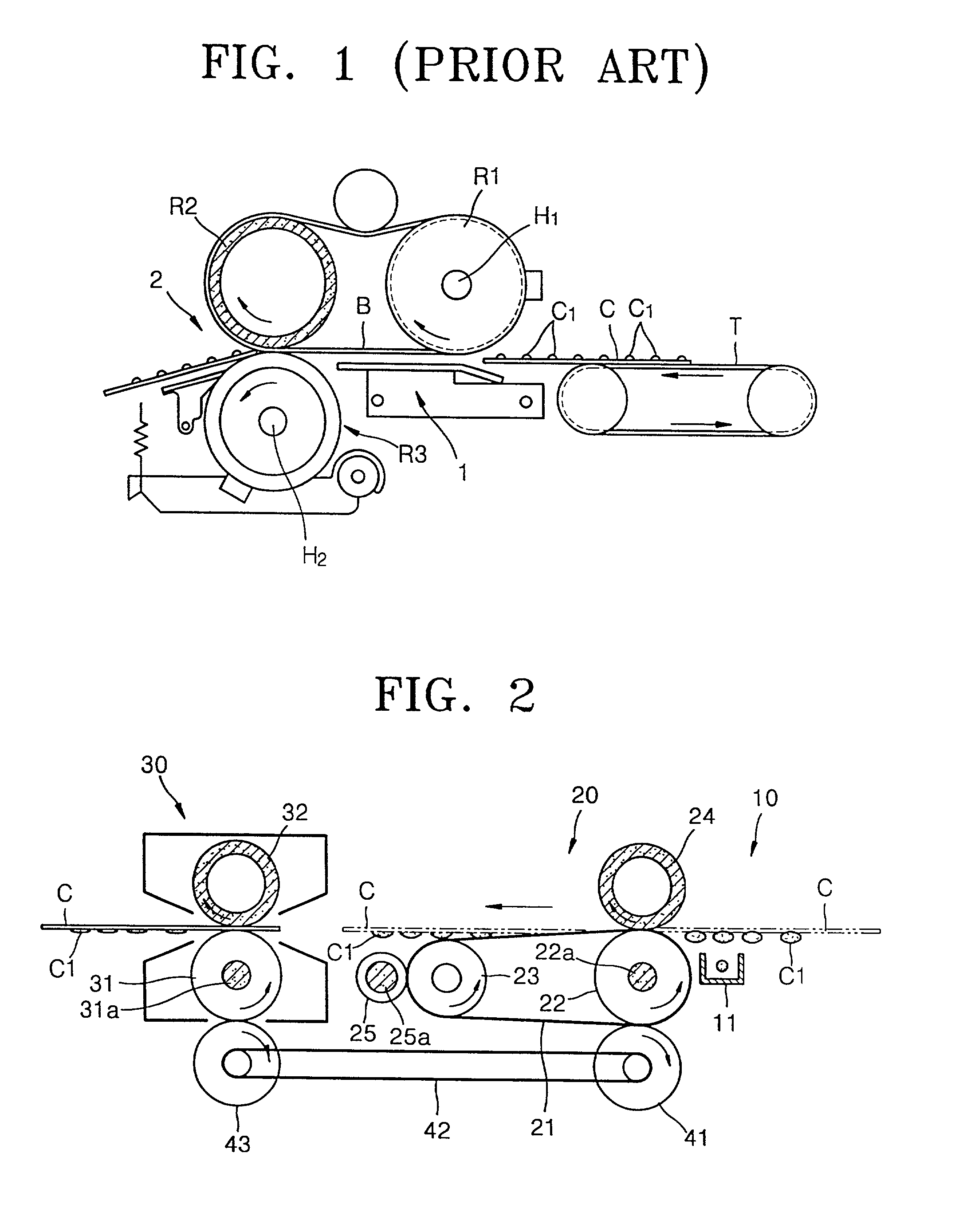
[0014] Referring to FIG. 2, an image fusing unit of a liquid electrophotographic printer according to an illustrative, non-limiting embodiment of the present invention includes a charging portion 10, a contact type drying portion 20, and a fusing portion 30. The charging portion 10 includes a charger 11 for forming electric potential on a path along which a sheet of paper C passes. The charger 11 forms an electric potential in a direction in which an image Cl of a developer transferred onto the paper C is pressed against the paper C. That is, since toner in the developer is typically charged to plus (+), as shown in the drawing, the surface of the paper C where the image Cl is transferred is charged to be relatively higher than the opposite surface thereof so that the toner is in close contact with the paper C by an electric force. This corresponds to a preliminary pressing step to prevent the toner from adhering to a drying belt 21 when the paper C passes through a contact type dry...


PUM


Abstract

An image fusing unit of a liquid electrophotographic unit for fusing an image developed by a developer which is a mixture of toner particles and liquid solvent and transferred onto a sheet of paper includes a charging portion installed on a transfer path of the paper for applying electric potential in a direction in which the toner is in close contact with the paper, a drying portion for drying the image by directly contacting and heating the paper, and a fusing portion for fixing the image to the paper by heating and pressing the paper. Thus, the efficiency of heat can be improved by drying in the direct contact method. Also, by closely pressing the toner against the paper prior to drying, the disadvantage according to the contact type drying method, that is, the toner adheres to a contact member, can be solved.

Description

[0001] 1. Field of the Invention[0002] An apparatus consistent with the present invention relates to an image fusing unit of a liquid electrophotographic printer.[0003] 2. Description of the Related Art[0004] In a typical liquid electrophotographic printer such as a color laser printer, a desired image is developed on a photosensitive medium with a developer liquid mixture of charged toner particles and solvent, and then, the developed image is transferred to a sheet of print paper.[0005] However, since the image transferred onto the print paper includes a large amount of solvent, an image fusing unit is needed to dry the image after transfer and completely fuse it on the print paper.[0006] FIG. 1 shows a conventional image fusing unit for drying and fusing which is disclosed in U.S. Pat. No. 5,465,146. As shown in the drawing, the image fusing unit includes a drying portion 1 for drying a sheet of paper C where an image C1 is transferred in a non-contact manner, and a fusing portio...

Claims


Application Information

Patent Timeline
Patent Type & Authority Applications(United States)
IPC IPC(8): G03G15/11G03G15/20
CPCG03G15/11G03G15/2064G03G2215/00666
Inventor PANG, JEONG-HUNKANG, DONG-HWAN
Owner S PRINTING SOLUTION CO LTD
Why Eureka
Try Eureka