Firearms display & storage safe

a technology for storage safes and firearms, applied in the direction of safes, wing accessories, wing arrangements, etc., can solve the problems of insufficient use of storage space, material economic detriment, and insufficient empty dedicated display areas

Inactive Publication Date: 2003-03-06
GERSTENKORN EDWARD F
View PDF0 Cites 12 Cited by
  • Summary
  • Abstract
  • Description
  • Claims
  • Application Information

AI Technical Summary

Benefits of technology

[0009] The backing of all portions of the display case are made of heavy steel plate, or suitable vault grade laminate, or other material suitable for use in a secure storage vault in substitution of heavy steel plate. The display case is configured such that with minimal movements and effort the moveable doors of the display case may be folded forward and inward as permitted by the hinges connecting the moveable doors to the fixed partial side plates. Defined within and about the moveable doors and other portions of the main body of the display case and storage safe are secure closure means including metal bolts (such as "pins") and receiving apertures for said metal bolts, cooperatively coupled via mechanical linkages to a locking device accessible from the exterior of one of the moveable doors. The mechanical linkages move the metal bolts laterally and / or vertically to secure the moveable doors to the main body and to each other by way of the receiving apertures located therein. The locking device may be any suitable locking device, including a digital or rotary locking device. When the moveable doors are closed, the display case with heavy steel plate becomes a secure storage safe, with fire resistant seals and materials, having fixable mounting means for the displayed firearms configured and arranged so that upon closing of the moveable doors the firearms, previously displayed, are (i) securely enclosed within the cavity of the storage safe, and (ii) restrained and fixed to their respective display surfaces so that the impetus resultant of shutting movement velocities and stopping decelerations of the moveable doors is incapable of dislodging the mounted firearms from their display components. Result: The display case is able to be readily, rapidly and easily transformed into a secure storage safe meeting all regulations, and firearms previously displayed during the present inventions display mode become safely encapsulated and stored within the cavity of the display case now turned secure storage safe.
[0016] It is yet a further object of the present invention to provide an effective method and system for the display and secure storage of firearms that eliminates both the need for any transfer of the firearms and the need for a separate secure storage safe, thereby eliminating both wasteful use of space and tedious and risky transfer effort.

Problems solved by technology

The recurrent daily transfer of the handguns and other firearms from secure storage to display cases and back poses several problems, some of which are of material economic detriment to the merchant.
For one, store space is not being used efficiently, as during business hours the space dedicated to the secure storage is not in use, and during non-business hours that space dedicated to the display area is necessarily left empty.
Square footage in desired business regions is almost always priced to a maximum level the market will bear, and a continual non-use of such space is wasteful and burdensome upon the merchant.
None of the current art teaches a system or apparatus for the display and / or storage of firearms that solves this problem.
As a result, considering the above mentioned regulation requiring that all handguns which are on daily display must be secured in safes or vaults during non-business hours, in light of the failure of the prior art to present a viable alternative to such daily transfer, the costly non-use of business zoned square footage is essentially forced upon the merchant.
Other problems associated with a daily transferring of handguns or other firearms result from the fact that guns and other firearms are essentially made aesthetically appealing, and subsequently have a certain variety of delicateness.
Therefore, in an attempt to preserve the full value of the rather costly merchandise, the firearms must be moved with great care, requiring substantial time.
As many gun stores are operated by their proprietors, the matter is not one only of an economic waste, but one of lost personal time, and increased fatigue, upon already heavily worked individuals.
This poses personal safety risks as well, especially because stores selling handguns and firearms are most likely to be targeted by thieves after closing; i.e. when most stores are secured, but a firearm sole proprietor may be occupied delicately removing, transferring, and carefully positioning in secure storage a large quantity of valuable items he is attempting to prevent the damage of.

Method used


Image

  • Firearms display & storage safe
  • Firearms display & storage safe
  • Firearms display & storage safe

Examples


Embodiment Construction

)

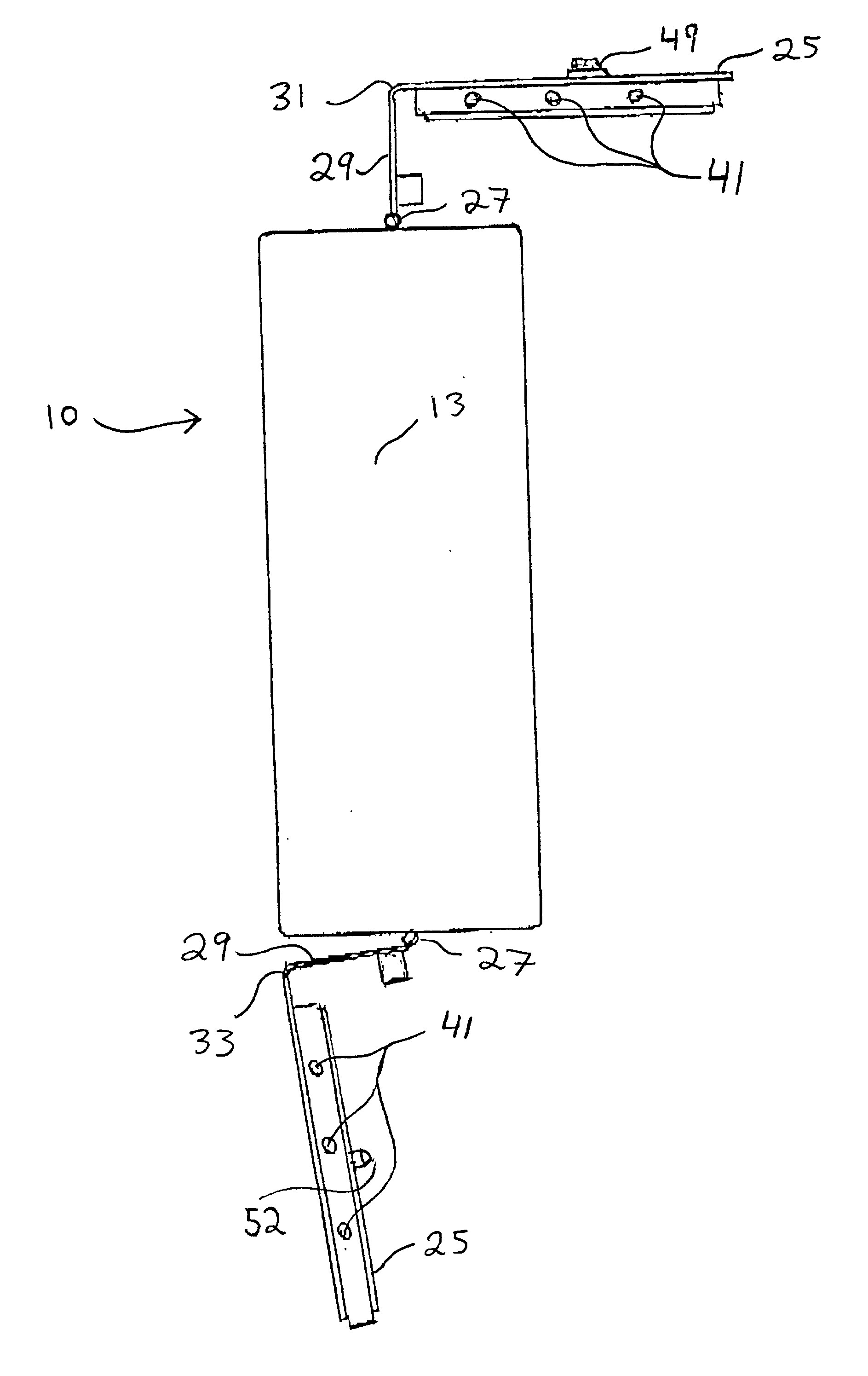
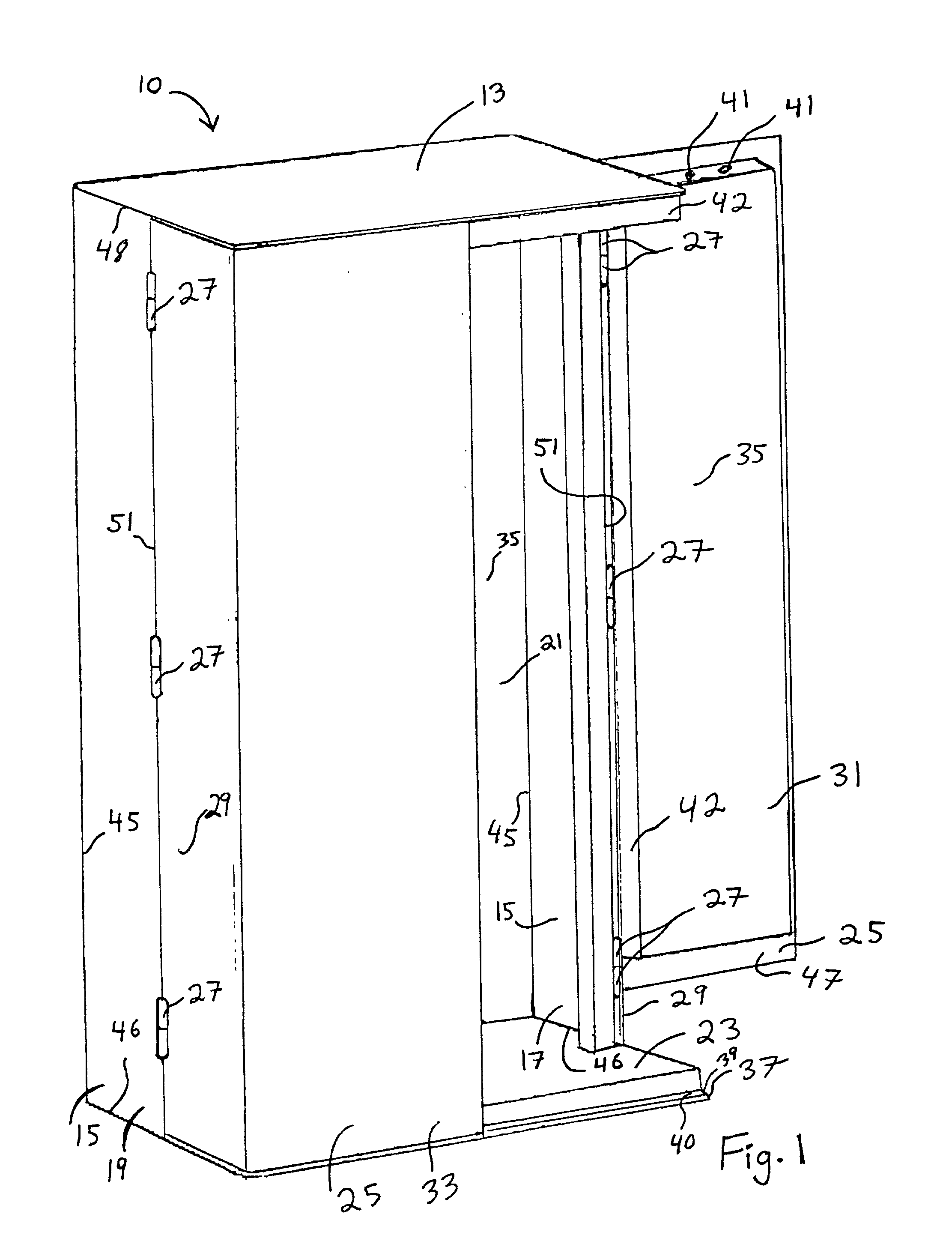
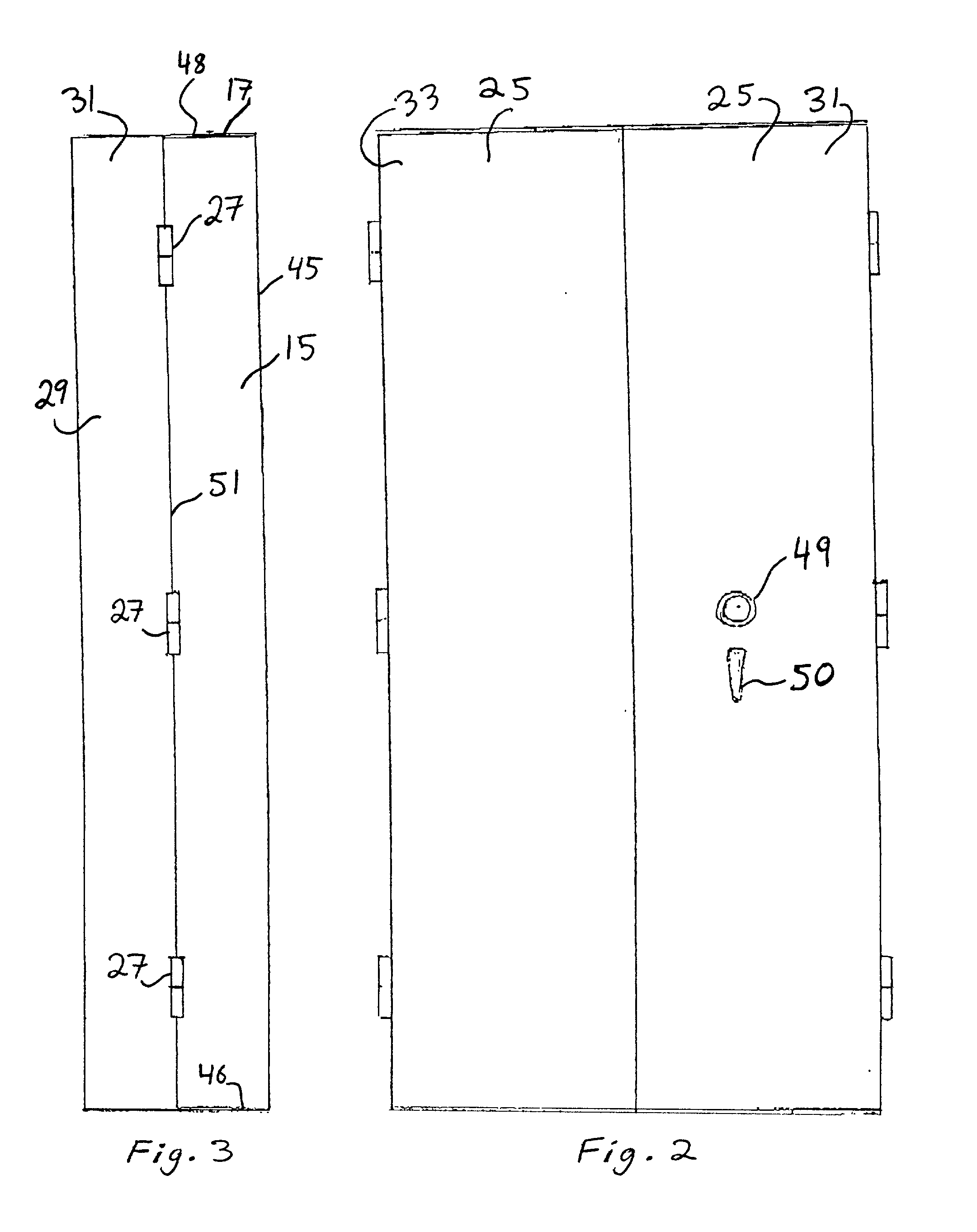
[0026] Referring to FIG. 1 a firearms display case and storage safe main body as generally indicated by arrow line 10 includes fixed top plate 13, fixed partial side plates 15, including fixed left partial side plate 17 and fixed right partial side plate 19, a fixed back plate 21, fixed bottom plate 23, and moveable doors 25. Moveable doors 25 are moveably attached to fixed partial side plates 15 by maximally strong tamper resistant hinges 27 attached to fix partial side plates 15 at the shorter sides 29 of moveable doors 25. Each fixed partial side plate 15 has four (4) sides: back side 45 attached to fixed back plate 21, bottom side 46 attached to fixed bottom plate 23, top side 48 attached to fixed top plate 13, and fourth side 51 to which are connected via hinges 27 moveable doors 25. Moveable doors 25 include left and right moveable doors 31 and 33, respectively. In FIG. 1 only the inside surfaces of fixed back plate 21 and left moveable door 31 are visible. Similarly not visi...


PUM


Abstract

A firearms storage safe which transforms into a display case for firearms contained therein.

Description

FIELD OF THE INVENTION[0001] This invention relates generally to a firearms storage safe which transforms into a display case suitable for use in public gun stores.DESCRIPTION OF THE PRIOR ART[0002] Counter-type display cases are widely employed as a means of displaying firearms for sale in gun stores. Frequently, these cases have frames made of wood or metal with fronts and tops of glass. Current federal law requires that all handguns that are on daily display must be secured in safes or vaults during non-business hours. Each morning the handguns must be moved from secure storage to the display cases, and each evening the handguns must be returned to secure storage.[0003] The recurrent daily transfer of the handguns and other firearms from secure storage to display cases and back poses several problems, some of which are of material economic detriment to the merchant. For one, store space is not being used efficiently, as during business hours the space dedicated to the secure stor...

Claims


Application Information

Patent Timeline
Patent Type & Authority Applications(United States)
IPC IPC(8): A47B81/00A47F3/00A47F7/00E05B65/00E05G1/00E05G1/04
CPCA47B81/005A47F3/002A47F7/00E05B65/0075E05G1/00E05G1/04E05Y2900/20
Inventor GERSTENKORN, EDWARD F.
Owner GERSTENKORN EDWARD F
Why Eureka
Try Eureka