Bi-directional oscillation leg massager

a massager and bi-directional technology, applied in the field of massage equipment, can solve the problem of insignificant massage effect, and achieve the effect of high massage

Inactive Publication Date: 2003-03-13
LIFEGEAR INC
View PDF0 Cites 19 Cited by
  • Summary
  • Abstract
  • Description
  • Claims
  • Application Information

AI Technical Summary

Benefits of technology

[0003] According to the present invention, there is provided a bi-directional oscillation leg massager, which oscillates the user's legs in transverse direction as well as longitudinal direction to achieve high massaging effect when operated. To accomplish this, the inventive bi-directional oscillation leg massager comprises a housing, a power drive mounted in the housing and adapted to output a rotary driving force, and a combination oscillation mechanism. The combination oscillation mechanism has a drive member for synchronous rotation with the power drive, a first driven member adapted to reciprocate in a first linear path upon rotation of the drive member, a second driven member adapted to reciprocate in a second linear path not parallel to the first linear path upon reciprocation of the first driven member, and a guide member coupled between the first driven member and the second driven member and adapted to guide reciprocating motion of the second driven member in the second linear path. A support block is fastened to the second driven member and is adapted to support the user's legs.

Problems solved by technology

Because these oscillation leg massagers only oscillate the user's legs in transverse direction, the massaging effect is insignificant.

Method used


Image

  • Bi-directional oscillation leg massager
  • Bi-directional oscillation leg massager
  • Bi-directional oscillation leg massager

Examples


Embodiment Construction

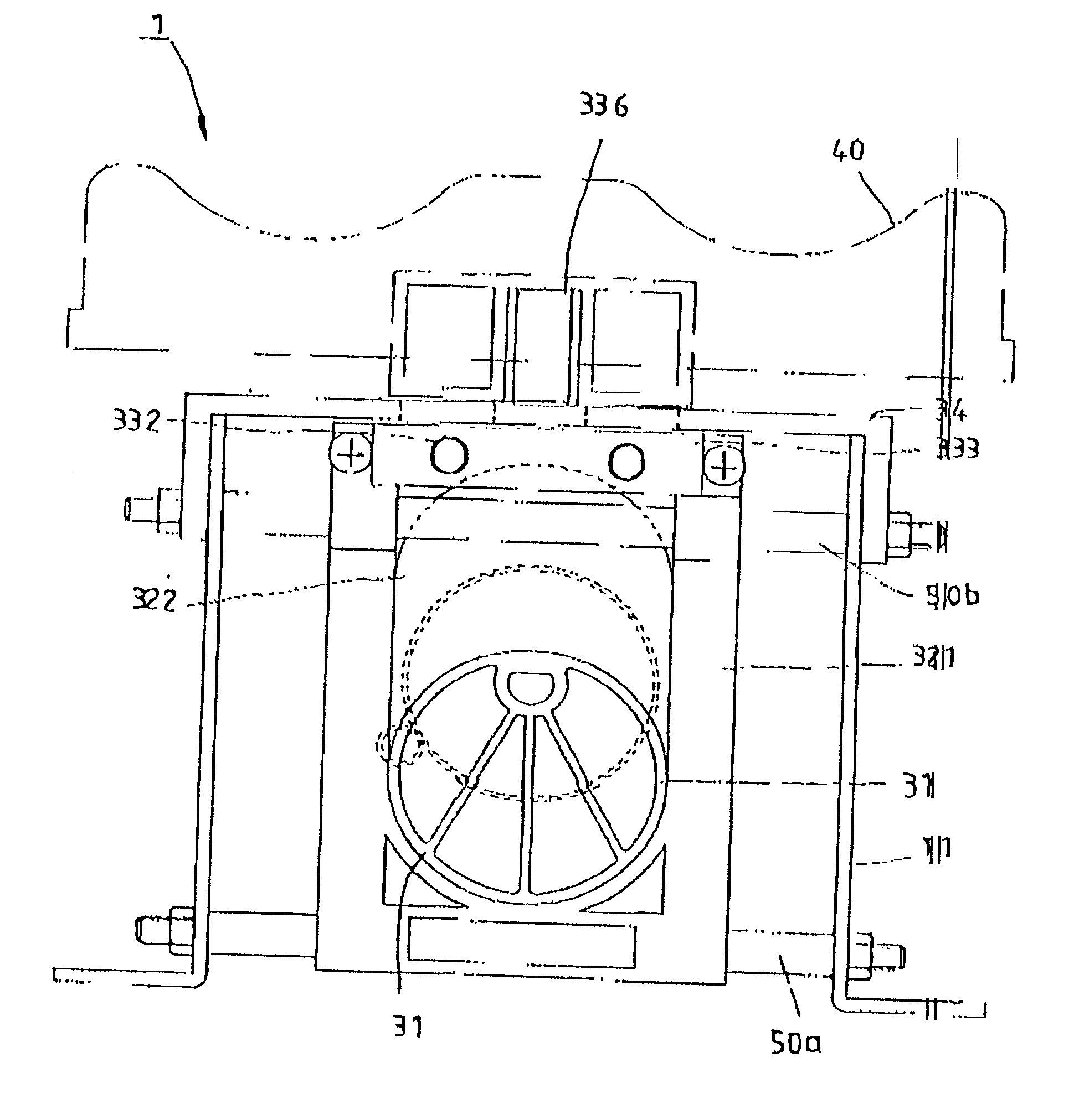
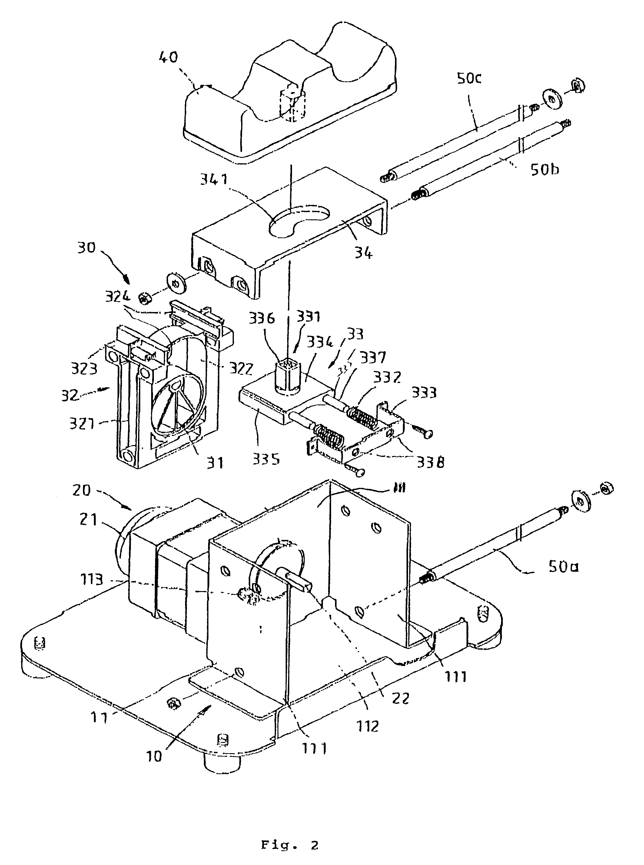
[0011] Referring to the drawings, the inventive bi-directional oscillation leg massager comprises a housing 10, a power drive 20, a combination oscillation mechanism 30, and a support block 40, as best seen in FIG. 2.

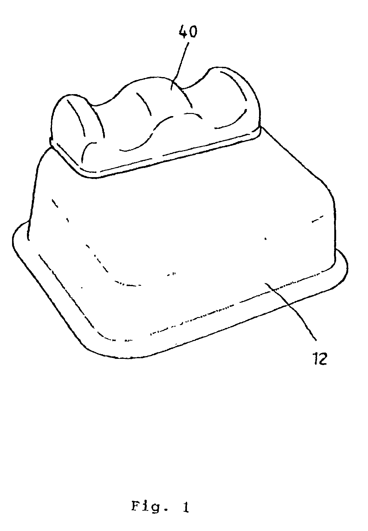
[0012] The housing 10 is comprised of an inner casing 11 and an outer casing 12 (FIG. 1). The inner casing 11 comprises three peripheral sidewalls 111 defining an open chamber 112. A receiving hole 113 in one peripheral sidewall 111 is in communication between the open chamber 112 and the space outside the inner casing 11. The outer casing 12 covers the inner casing 11, making the housing 10 attractive, as best seen in FIG. 1.

[0013] The power drive 20 is adapted to output a rotary driving force subject to a predetermined revolving speed, and comprises a motor 21, a transmission gear set (not shown), and a power output shaft 22. The transmission gear set is coupled between the motor 21 and the power output shaft 22. When starting the motor 21, the power output shaft 22 i...


PUM


Abstract

A bi-directional oscillation leg massager including a housing, a power drive mounted in the housing and adapted to output a rotary driving force, and a combination oscillation mechanism. The combination oscillation mechanism includes a drive member for synchronous rotation with the power drive, a first driven member adapted to reciprocate in a first linear path upon rotation of the drive member, a second driven member adapted to reciprocate in a second linear path not parallel to the first linear path upon reciprocation of the first driven member, and a guide member coupled between the first driven member and the second driven member and adapted to guide reciprocating motion of the second driven member in the second linear path. A support block is fastened to the second driven member and is adapted to support the users legs.

Description

BACKGROUND OF THE INVENTION[0001] The present invention relates to massaging apparatus and, more specifically, to a bi-directional oscillation leg massager that oscillates the user's legs in transverse direction as well as longitudinal direction when operated.[0002] Regular commercially available oscillation leg massagers commonly use a power drive to reciprocate an oscillation mechanism, so as oscillate the user's legs in transverse direction. Because these oscillation leg massagers only oscillate the user's legs in transverse direction, the massaging effect is insignificant. It would therefore be desirable to provide a powered leg massager which oscillates the user's legs both longitudinally and transversely so as to be more effective.SUMMARY OF THE INVENTION[0003] According to the present invention, there is provided a bi-directional oscillation leg massager, which oscillates the user's legs in transverse direction as well as longitudinal direction to achieve high massaging effec...

Claims


Application Information

Patent Timeline
Patent Type & Authority Applications(United States)
IPC IPC(8): A61H23/02
CPCA61H23/0254A61H2001/0251A61H2201/164A61H2201/1666A61H2201/1669A61H2203/0456A61H2205/10
Inventor HSIEH, PAULLIN, LAWRENCE
Owner LIFEGEAR INC
Why Eureka
Try Eureka