Massage machine and chair-type massage apparatus

a massage machine and chair-type technology, applied in the field of massage machines and chair-type massage apparatuses, can solve the problems of increasing the number of times the massage is performed on the treatment site, prolonging the time required for stroke massage, and unable to change the orientation of the leg, so as to achieve efficient stroke massage and favorable stroke massage

Inactive Publication Date: 2010-12-09
FAMILY INADA
View PDF9 Cites 14 Cited by
  • Summary
  • Abstract
  • Description
  • Claims
  • Application Information

AI Technical Summary

Benefits of technology

[0009]For this reason, even when massage is performed on the treatment site, the massage effect is limited to only a part of the treatment site.
[0010]Accordingly, in consideration of the above-mentioned problems, the present invention is intended to provide a massage machine and a chair-type massage apparatus capable of efficiently performing stroke massage by making a pair o

Problems solved by technology

As a result, the number of times the massage is performed on the treatment site increases, and the time required for the stroke massage is prolonged.
Furthermore, when the treatment site is a leg, the orientation of the leg cannot be chan

Method used


Image

  • Massage machine and chair-type massage apparatus
  • Massage machine and chair-type massage apparatus
  • Massage machine and chair-type massage apparatus

Examples


first embodiment

[0060]FIGS. 1 to 7 show a massage machine according to the present invention.

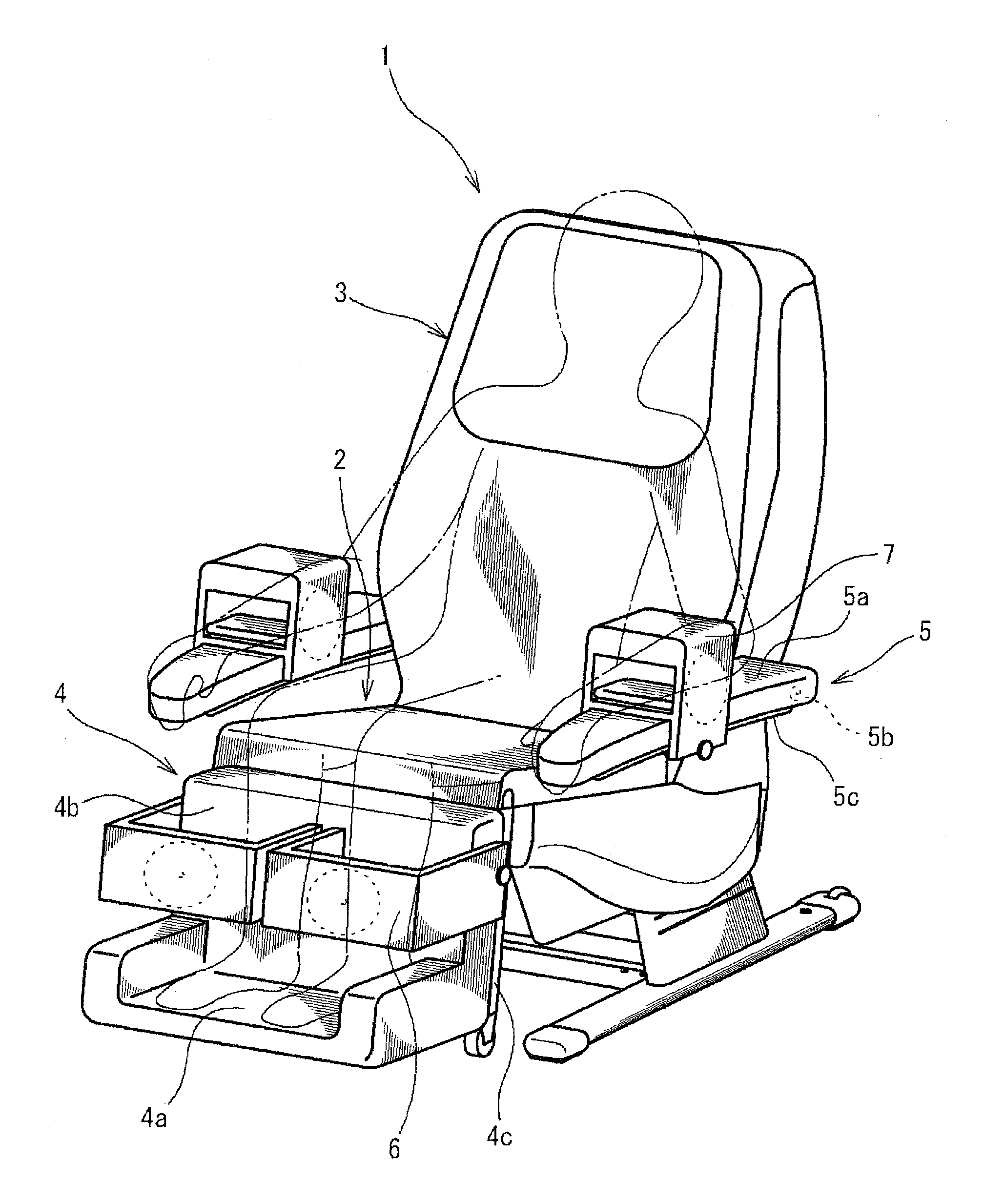
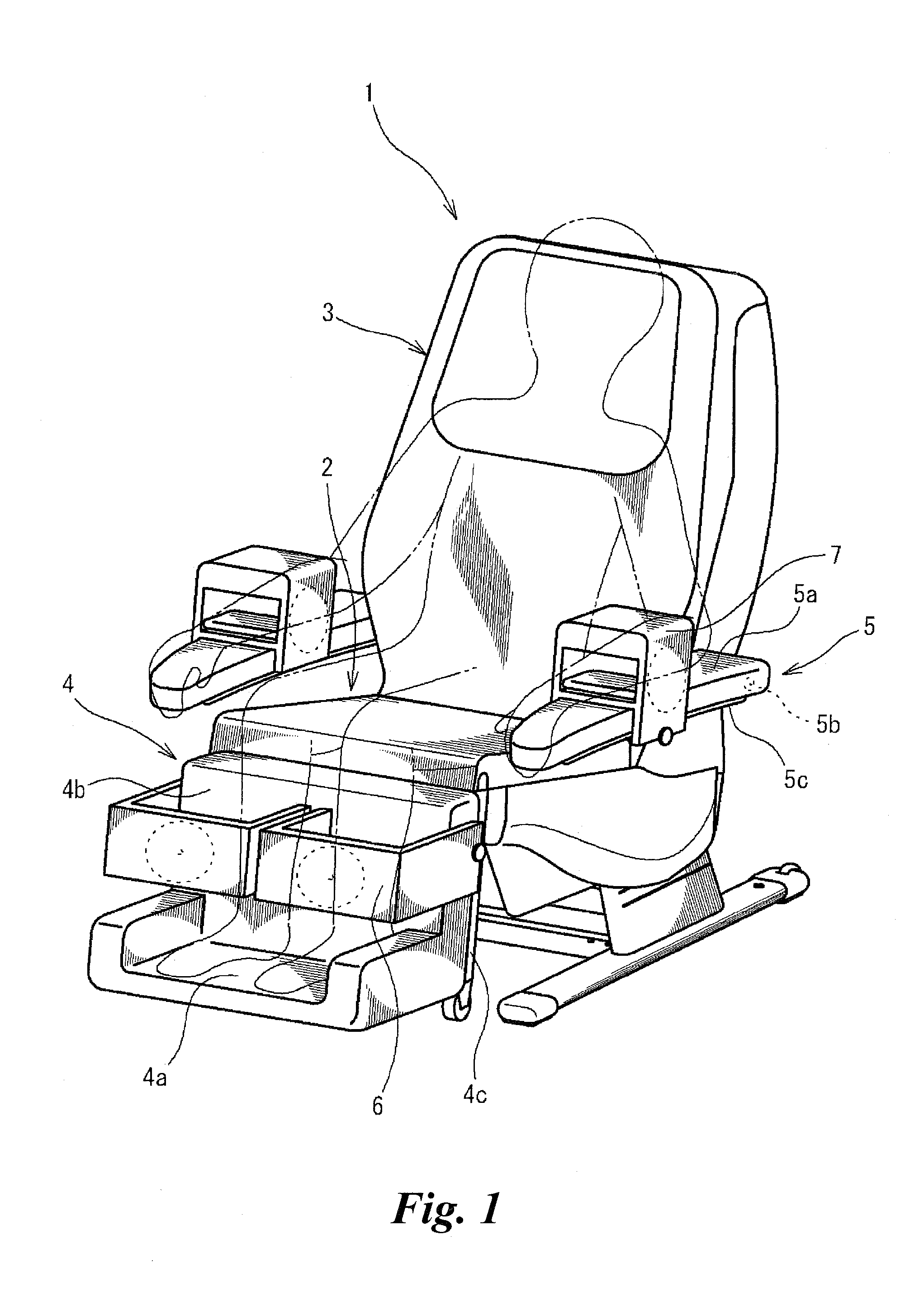
[0061]FIG. 1 is a perspective view showing a chair-type massage apparatus 1 equipped with the massage machine according to the first embodiment. This chair-type massage apparatus includes a seat section 2, a backrest section 3 disposed behind the seat section 2, a footrest section 4 disposed in front of the seat section, and armrest sections 5 disposed on both the left and right sides of the seat section 2.

[0062]In this embodiment, the height direction of the backrest section 3 being in the state shown in FIG. 1 is the up-down direction thereof, the depth direction thereof is referred to as the front-rear direction, and the width direction of the backrest section 3 as viewed from the front is referred to as the left-right direction.

[0063]The backrest section 3 is installed on the seat section 2 so that it can be reclined (rotated) backward.

[0064]The footrest section 4 is installed on the seat section 2 so a...

second embodiment

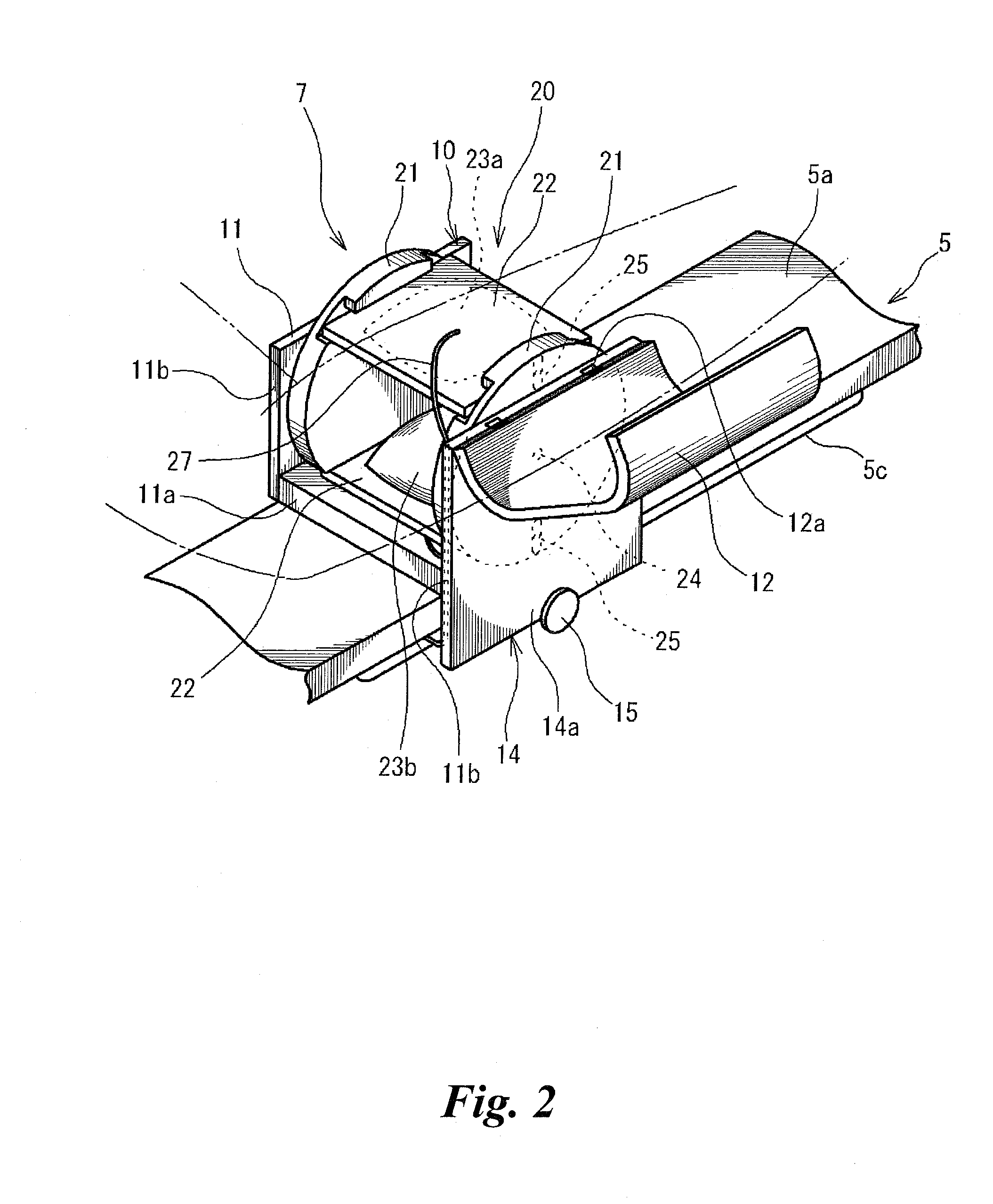
[0107]FIGS. 8 to 11 show a massage machine according to the present invention. The right arm massage machine 7 shown in FIGS. 8 to 11 is equipped with a massaging mechanism 40 having a link mechanism, such as a mechanism for adjusting the opposed distance between a pair of support plates, different from the above-mentioned massaging mechanism 20.

[0108]This massaging mechanism 40 is equipped with a pair of treatment devices 43 disposed opposite to each other at a given distance therebetween in the up-down direction, a pair of support plates (a first support: a support member) 42 for supporting the pair of treatment devices 43 from the outside in the up-down direction, a distance adjustment portion 48 for adjusting the opposed distance between the pair of support plates 42, a pair of rotation portions (a second support: a support member) 41 for applying a drive force to the pair of support plates 42 in the front-rear direction (the second direction) and for supporting the support plat...

third embodiment

[0136]FIGS. 16 to 19 show a massage machine according to the present invention.

[0137]The right arm massage machine 7 shown in FIGS. 16 to 19 is equipped with the above-mentioned massaging mechanism 20, a pressing direction adjustment portion 70 having a gear mechanism for rotating the massaging mechanism 20 in the circumferential direction of a treatment-site arm (for changing the first direction), and an outer frame 60 for accommodating the massaging mechanism 20 and the pressing direction adjustment portion 70 so that the massaging mechanism can rotate in the circumferential direction of the treatment-site arm.

[0138]The outer frame 60 has an accommodation portion 61, opened in the upper portion thereof and in the front-rear direction, for accommodating the massaging mechanism 20, a cover portion 62 for covering the accommodation portion 61 and the upper portion of the massaging mechanism 20 accommodated, and an installation portion 64 for accommodating and installing the pressing ...


PUM


Abstract

A massage machine equipped with air cells (23a, 23b) disposed opposite to each other at a given distance therebetween in the up-down direction, a pair of support plates (22, 22) for supporting the air cells (23a, 23b) from the outside in the up-down direction, a pair of rotation portions (21) for applying a drive force to the pair of support plates (22, 22) in the front-rear direction and for supporting the support plates (22, 22) on both the left and right sides, guide portions (25) formed in the pair of rotation portions (21) to support the pair of support plates (22) so that the pair of support plates is movable in a direction in which the support plates (22) approach and separate from each other, biasing portions (26) for biasing the pair of support plates (22) in a direction in which the support plates approach each other, and a drive unit (28) for applying a rotation drive force to the rotation portions (21).

Description

TECHNICAL FIELD[0001]The present invention relates to a massage machine and a chair-type massage apparatus capable of performing stroke massage to the user.BACKGROUND ART[0002]As a conventionally known massage machine capable of performing stroke massage to the user, the massage machine disclosed in JP-2004-202207-A is available.[0003]The footrest of the massage machine described in this document has a support base for supporting a treatment site and a movement portion disposed so as to be opposed to the support base so that the treatment site is held therebetween. The movement portion has a roller that is movable in the longitudinal direction of the treatment site, and the support base and the roller each have an air bag constituting a treatment unit.[0004]Furthermore, in this massage machine, the treatment units provided on the support base and the roller of the movement portion hold the treatment site therebetween and apply pressing stimulus to the treatment site. Moreover, opera...

Claims


Application Information

Patent Timeline
IPC IPC(8): A61H7/00
CPCA61H9/0078A61H2201/0103A61H2201/0149A61H2201/5007A61H2205/06A61H2205/10
Inventor FUKUYAMA, YOSHIFUMISHINOMIYA, DAISUKE
Owner FAMILY INADA
Why Eureka
Try Eureka