
Ventilation tube connection system

a technology of ventilation tube and connection system, which is applied in the field of endotracheal tubes, can solve the problems of causing death, causing dangerous patient situation, and causing "pop-off" events, and achieve the effect of preventing accidental po

Inactive Publication Date: 2003-06-12
BISON CREEK INNOVATIONS
View PDF0 Cites 7 Cited by
  • Summary
  • Abstract
  • Description
  • Claims
  • Application Information

AI Technical Summary

Benefits of technology

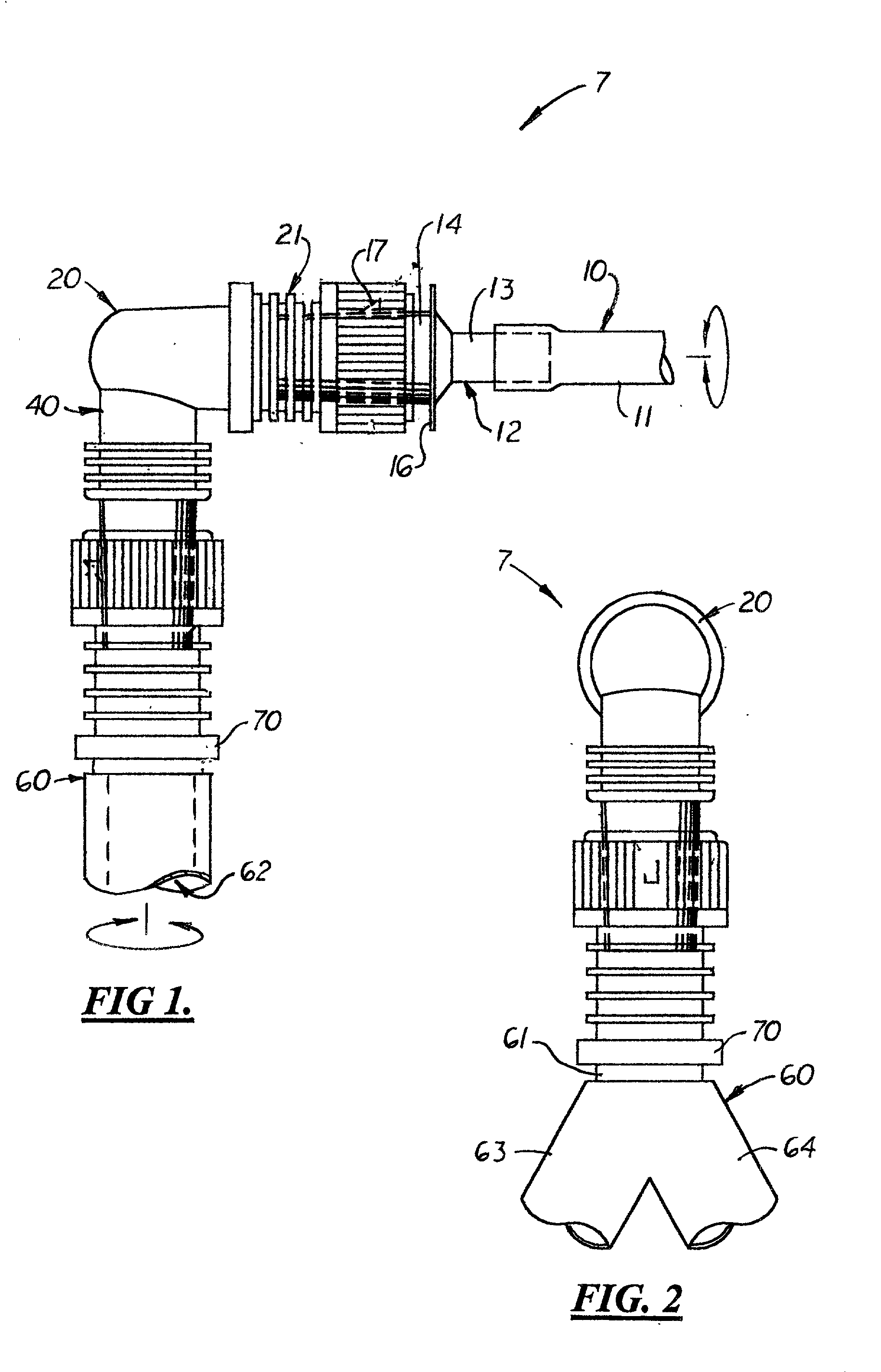
[0014] When assembled, the rotating leg member, the rotating coupler and the two adjustable collars enable the medical worker to selectively adjust the relative axial orientation of the end adapter on the rotating leg member and the axial orientation of the rotating coupler on the long leg section. When the components are adjusted for greater comfort, the end adapter and rotating coupler are locked in their respective axial positions on the rotating and fixed leg members, respectively. Since the rotating leg member and the rotating coupler are not axially locked in position on the elbow connector and on the ventilator connection tube, respectively, they may axially rotate when torque forces are applied thereto by the endotracheal and ventilator connection tubes thus preventing accidental "pop-offs".

Problems solved by technology

The connectors between the ends of the ventilation tube and the endotrachael tube utilize a friction-fit connector, which accidentally disconnects and results in an event known as "pop-off".
Disconnection of the connector precludes mechanical ventilation assistance, thereby creating a hazardous situation for the patient.
For patients in a home setting who are not under continuous supervision by medical personnel, "pop-off" events can be fatal.

Method used


Image

  • Ventilation tube connection system
  • Ventilation tube connection system
  • Ventilation tube connection system

Examples


Embodiment Construction

)

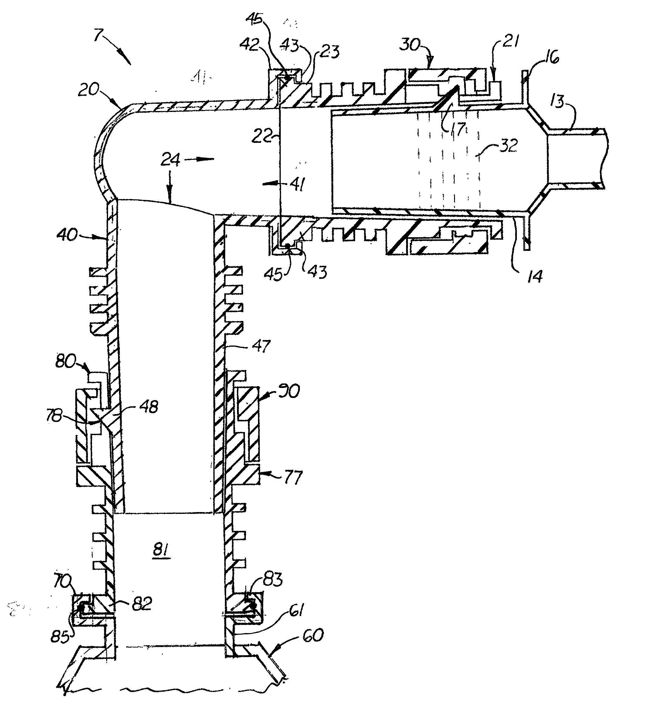
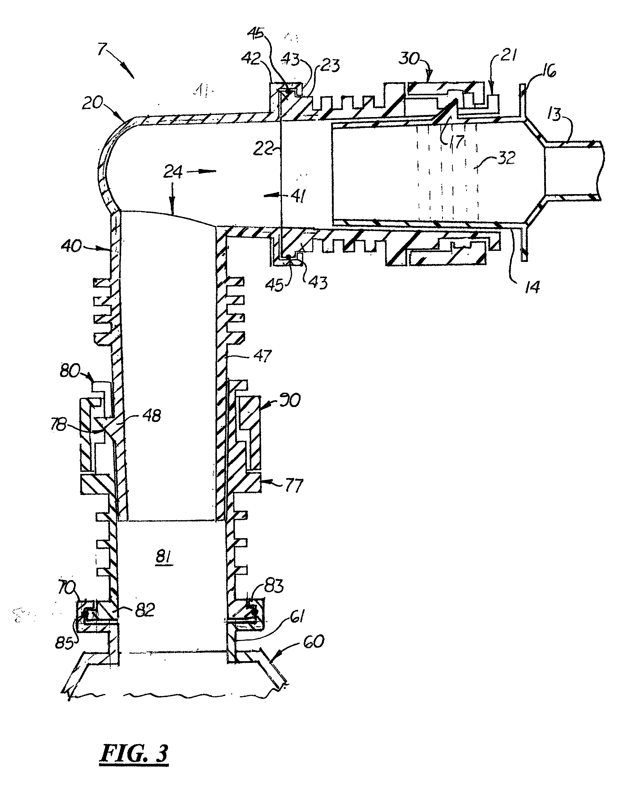
[0026] An improved ventilation tube connection system, generally designated as 7, is disclosed that includes a modified endotracheal tube 10, an elbow connector 20, and a modified ventilation tube 60. The modified endotracheal tube 10 is similar to a standard endotracheal tube with a standard main tube section 11 having an integrally formed or adhesively attached end adapter 12 located on its distal end. The end adapter 12, shown more clearly in FIGS. 3-5, is a hollow, cylindrical-shaped structure with a narrow main tube connecting section 13 and a wide section 14. Formed on the outer surface of the wide section 14 is a laterally extending key 17. The wide section 14 is slightly conical in shape and narrows towards its distal end. Integrally formed on the wide section 14 adjacent to the main tube connecting section 13 are laterally extending gripping ears 16 that, during use, may be held by medical personnel to connect the elbow connector 20 to the modified endotracheal tube 10. Du...


PUM


Abstract

An improved ventilator connection tube system designed to improve patient comfort and prevent accidental "pop off" incidents that often occur with standard endotracheal and ventilation tubes. The system includes a modified endotracheal tube that includes a cylindrical-shaped end adapter, an L-shaped elbow connector with a rotating leg member and a fixed leg member, and a ventilator connection tube. In the preferred embodiment, the rotating leg member is perpendicularly aligned on one end of the fixed leg member and slidingly receives the end adapter on the modified endotracheal tube. Disposed around the rotating leg member is a first rotating collar that securely fixes the end adapter to the rotating leg member. The fixed leg member includes a long leg section that slidingly connects to a rotating coupler attached to the ventilator connection tube. A second rotating collar is disposed around the rotating coupler to selectively attach the fixed leg member to the rotating coupler. When the system is assembled, the rotating leg member and rotating coupler are able to selectively rotate over the ends of the elbow connector and the ventilator connection tube, respectively, thereby reducing forces exerted thereon. Optional O-rings are disposed inside each joint to provide airtight seals.

Description

[0001] 1. Field of the Invention[0002] This medical invention relates to endotracheal tubes, and more particularly, to endotracheal tubes with quick-connect and disconnect couplers resistant to accidental pop-offs.[0003] 2. Description of Prior Art[0004] Patients who are unable to breathe spontaneously require ventilation assistance. Such patients are typically connected to a ventilator, which provides continuous mechanical ventilation assistance.[0005] Connecting the patient to the ventilator requires the use of ventilation tubing that connects to an endotracheal tube placed through the patient's mouth and into the trachea. The connectors between the ends of the ventilation tube and the endotrachael tube utilize a friction-fit connector, which accidentally disconnects and results in an event known as "pop-off". Disconnection of the connector precludes mechanical ventilation assistance, thereby creating a hazardous situation for the patient. To eliminate "pop-off" events, medical pe...

Claims


Application Information

Patent Timeline
IPC IPC(8): A61M16/00A61M16/04A61M16/08
CPCA61M16/04A61M16/0084A61M16/08
Inventor CARDON, KERRIE
Owner BISON CREEK INNOVATIONS
Learn More