Fuel injection valve

a technology of fuel injector and valve body, which is applied in the direction of fuel injector pumps, machines/engines, mechanical equipment, etc., can solve the problems of connecting components, mechanical weakening of the valve housing or the seat carrier at the location, and damage to the fuel injector during operation

Inactive Publication Date: 2003-06-26
ROBERT BOSCH GMBH
View PDF5 Cites 11 Cited by
  • Summary
  • Abstract
  • Description
  • Claims
  • Application Information

AI Technical Summary

Problems solved by technology

One disadvantage of the known fuel injectors described above is in particular the mechanical weakening of the valve housing or the seat carrier at the location of the magnetic throttle.
Since the fuel injectors are designed mainly for direct injection of fuel into the combustion chamber of internal combustion engines having fuel mixture compression and spark ignition, high pressures prevail in the combustion chamber as well as in the fuel injector, potentially damaging the fuel injector during operation.
The connecting components normally used to reinforce the housing have the disadvantage that they must be made of a nonferritic material, independently of the internal pole and the external pole.
Assembly of the connecting components may also damage the housing, which is weak at this point.

Method used


Image

  • Fuel injection valve
  • Fuel injection valve
  • Fuel injection valve

Examples


Embodiment Construction

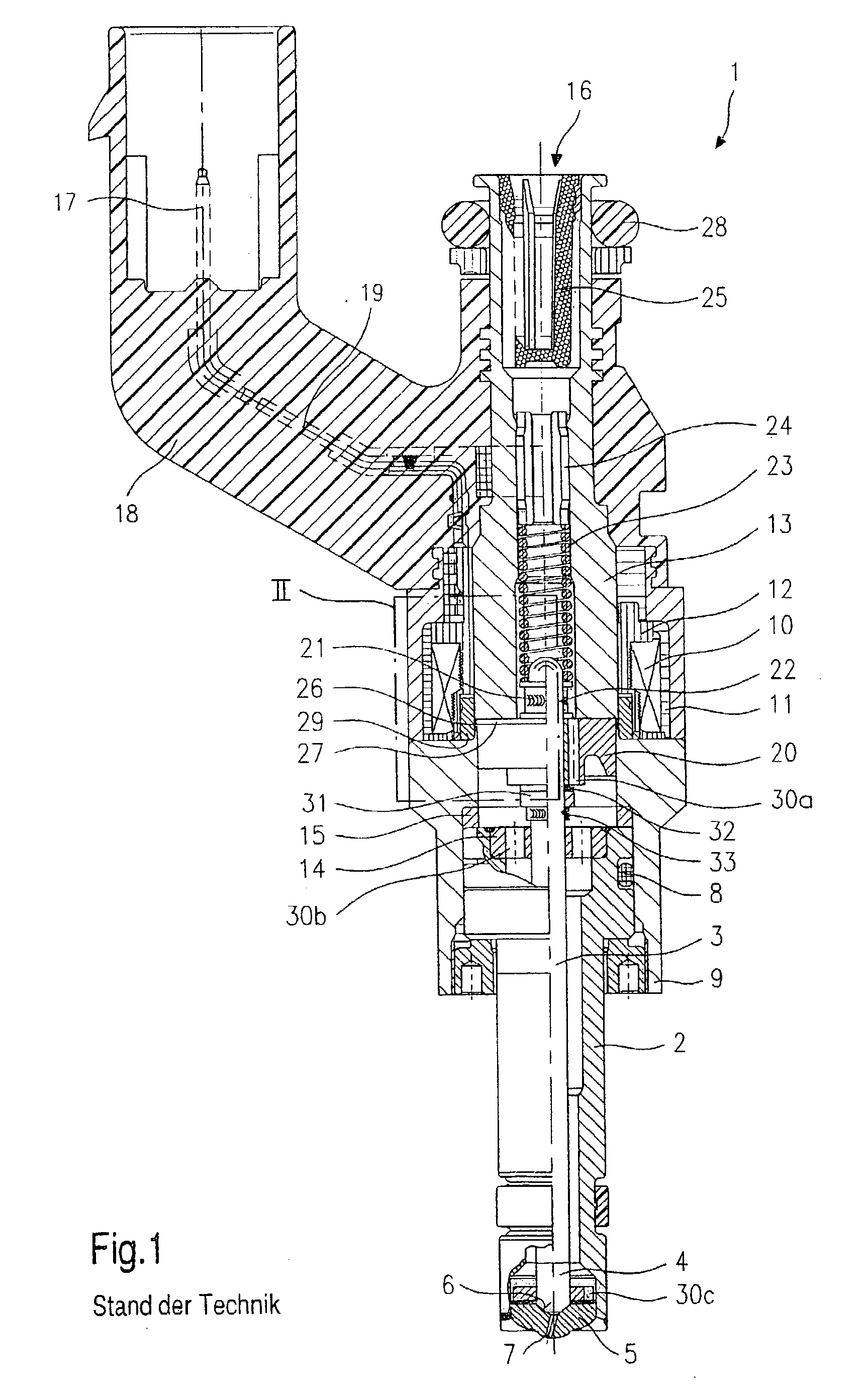
[0020] Before describing an embodiment of a fuel injector 1 according to the present invention on the basis of FIGS. 2 and 3, the essential components of a fuel injector according to the related art which has the same design except for the measures according to the present invention will now be explained briefly for a better understanding of the present invention on the basis of FIG. 1.

[0021] Fuel injector 1 is designed in the form of a fuel injector for fuel injection systems of engines having fuel mixture compression and spark ignition. Fuel injector 1 is suitable in particular for direct injection of fuel into the combustion chamber (not shown) of an engine.

[0022] Fuel injector 1 is made of a nozzle body 2 in which a valve needle 3 is situated. Valve needle 3 is mechanically connected to a valve-closure member 4, which cooperates with a valve-seat surface 6 on a valve seat body 5 to form a sealing seat. In this embodiment, fuel injector 1 is an inwardly opening fuel injector 1 wh...


PUM


Abstract

A fuel injector (1), in particular an injector for direct injection of fuel into a combustion chamber of a mixture-compressing, spark-ignition internal combustion engine has a solenoid (10), which cooperates with an armature (20), and a magnetic internal pole (13) and a magnetic external pole (9), the armature (20) being connected in a force-locking manner to a valve needle (3) for actuating of the fuel injector (1), the valve needle having on its injection end a valve-closure member (4), which cooperates with a valve seat (6). At least one permanent magnet (34) is situated in a connecting area between the internal pole (13) and the external pole (9).

Description

BACKGROUND INFORMATION[0001] The present invention relates to a fuel injector according to the preamble of the main claim.[0002] For magnetic throttling between the poles of an electromagnetically operable fuel injector, usually either a nonmagnetic intermediate component is used or the seat carrier or the valve casing is equipped with a thin-walled collar as a throttle, depending on the design of the fuel injector. The magnetic circuit rapidly approaches saturation in the throttle location due to the fact that the material has a small wall thickness.[0003] For operation of high-pressure fuel injectors, a connecting element or a supporting ring is mounted around the throttle location to mechanically reinforce the resulting mechanically weak spot.[0004] For example, German Patent Application 195 03 821 A1 describes a fuel injector in which the number of components of the valve tube is reduced so that the number of joints and connection points is also reduced. The entire valve tube is...

Claims


Application Information

Patent Timeline
Patent Type & Authority Applications(United States)
IPC IPC(8): F02B75/12F02M51/06
CPCF02B2075/125F02M51/0614Y02T10/123F02M51/0689F02M51/0671Y02T10/12
Inventor REITER, FERDINAND
Owner ROBERT BOSCH GMBH
Why Eureka
Try Eureka