Optical beam scanning system for compact image display or image acquisition

a scanning system and optical fiber technology, applied in the field of relativly compact optical fiber beam scanning system and method for displaying or acquiring images, can solve the problems of unnecessary additional optical coupling and alignment, complex design and fabrication of multiple actuators that drive mirror-based systems,

Active Publication Date: 2005-08-11
UNIV OF WASHINGTON
View PDF8 Cites 71 Cited by
  • Summary
  • Abstract
  • Description
  • Claims
  • Application Information

AI Technical Summary

Benefits of technology

[0007] In addition to its ultra-thin diameter, another major advantage of the micro-fabricated optical waveguide over mirror-based resonant optical scanners is its simplicity of design, fabrication, and assembly / packaging. Accordingly, the resonant waveguide optical scanner is extremely low cost in both fabrication and material unit costs. By comparison, the multiple actuators that drive a mirror-based system are complex in design and fabrication, whereas a single cheap actuator is all that is needed to drive a cantilevered portion of the custom waveguide into its resonant scanning patterns. In addition, a mirror scanner has the disadvantage of requiring optical alignment with the illuminating light source or optical fiber, whereas the custom optical waveguide can be micro-fabricated at the end of the optical fiber itself, so that additional optical coupling and alignment are unnecessary.
[0014] A spacer can be used for coupling the optical component to the distal end of the waveguide. The spacer is sized to make the vibratory node of the waveguide substantially coincident with the effective light source at the distal end of the waveguide. This position of the effective light source may also be substantially coincident or proximal to the back focal point of the optical element to achieve high field of view imaging.
[0016] Another aspect of the present invention is directed to a method for fabricating a compact optical scanner for scanning a region. The method includes the steps of providing a waveguide through which light is guided between a proximal end and a distal end of the waveguide. An optical component having a back focal point is attached to the distal end of the waveguide. A cross-sectional area of a portion of the waveguide adjacent to the distal end is then substantially reduced, leaving the distal end of the waveguide where the optical component is attached unaffected. An actuator is coupled to the waveguide to vibrate the portion of waveguide that is reduced in cross-sectional area at a desired frequency and in a desired pattern. Excitation of the waveguide by the actuator causes the optical component to rotate without substantial lateral displacement, so as to scan a region with light exiting the optical component.

Problems solved by technology

By comparison, the multiple actuators that drive a mirror-based system are complex in design and fabrication, whereas a single cheap actuator is all that is needed to drive a cantilevered portion of the custom waveguide into its resonant scanning patterns.
In addition, a mirror scanner has the disadvantage of requiring optical alignment with the illuminating light source or optical fiber, whereas the custom optical waveguide can be micro-fabricated at the end of the optical fiber itself, so that additional optical coupling and alignment are unnecessary.

Method used


Image

  • Optical beam scanning system for compact image display or image acquisition
  • Optical beam scanning system for compact image display or image acquisition
  • Optical beam scanning system for compact image display or image acquisition

Examples


Embodiment Construction

Construction of a Scanning Optical Fiber

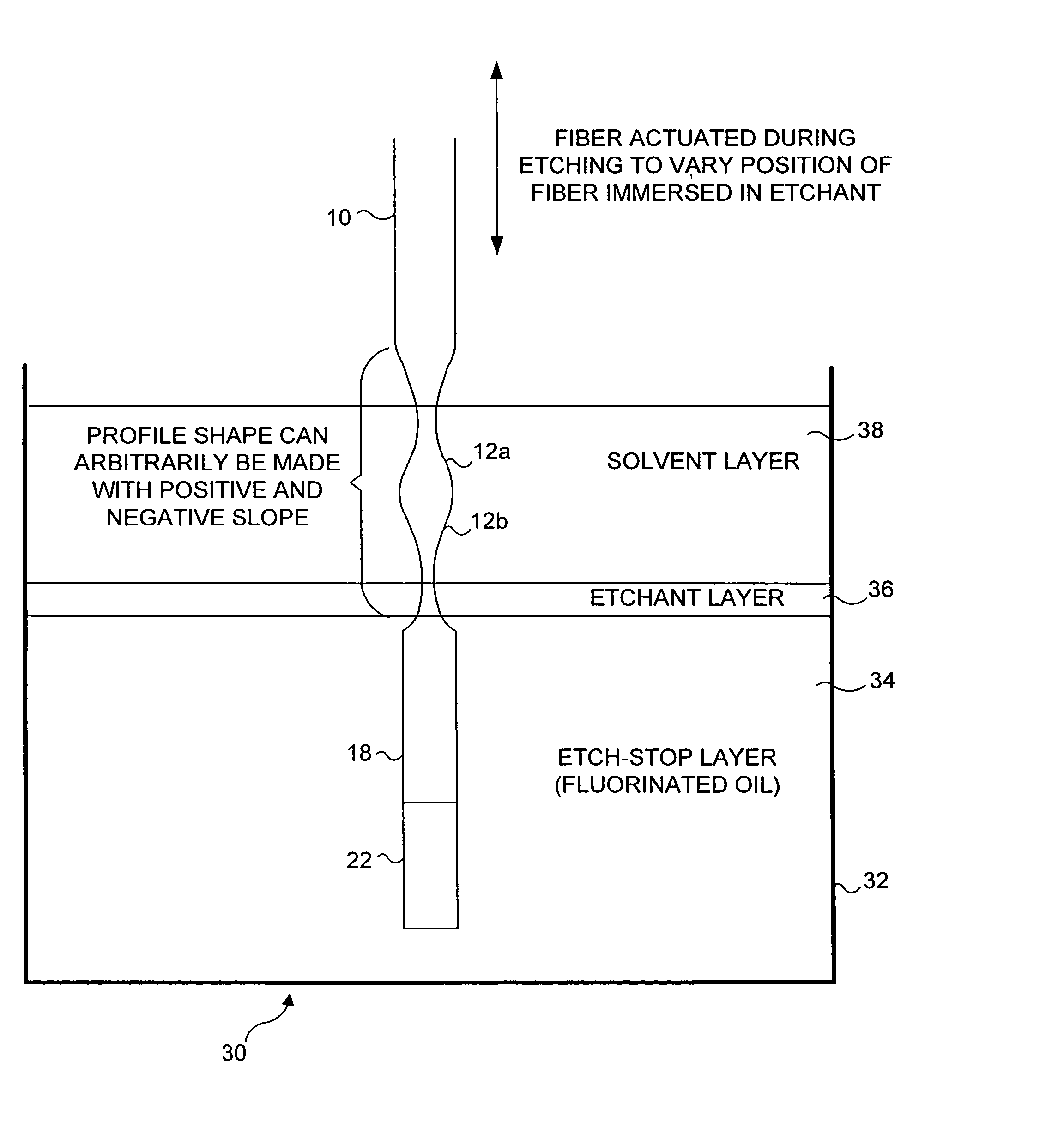
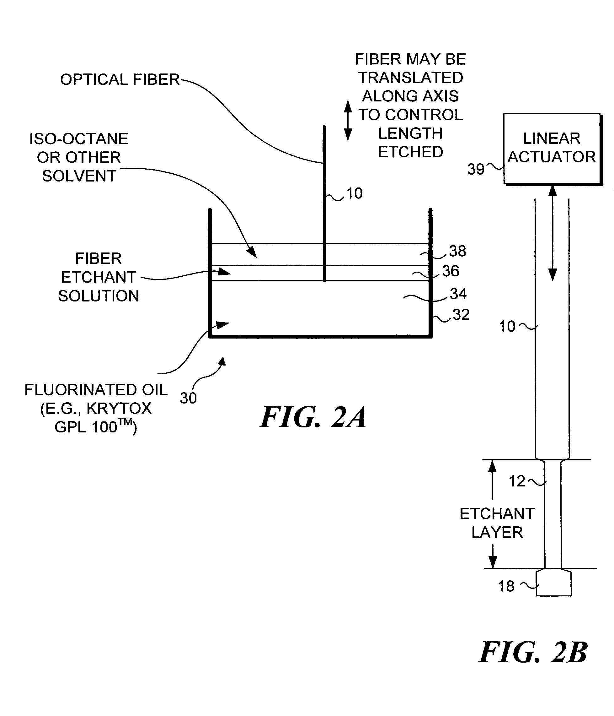
[0048] When using fusion splicing for joining an optical fiber to optical components (e.g., to a GRIN lens or larger core multimode optical fiber), it is preferable to carry out any etching of the optical fiber after the fusion splicing has been completed, because it is easier to work with the optical fiber during the fusion process before it is made more flexible by being etched to a reduced diameter. Optical fiber scanning applications rely on the reduced diameter and mass distributions along the optical fiber to produce a relatively wide FOV at video rate scan frequencies. However, the extremely small (e.g., about 10-50 microns) diameter of a distal tip 16 of an etched region 12 on an optical fiber 10 (typically single mode) makes the attachment of added optical components, such as a ball lens 14, to distal tip 16 difficult, as will be apparent from the example shown in FIG. 1A. Optical fiber scanning applications frequently require optic...


PUM

PropertyMeasurementUnit
frequenciesaaaaaaaaaa
diameteraaaaaaaaaa
diameteraaaaaaaaaa

Abstract

An optical fiber having a reduced cross-sectional region adjacent to its distal end, which is fused to an optical component, is vibrated, rotating the optical component to scan a region. The optical component has a back focal point that is substantially coincident with an effective light source of the optical fiber, so that the light emanating from the optical component is either substantially collimated or convergent. The optical component is either a ball lens, a drum lens, a graded index lens, or a diffractive optical element. A vibratory node is also made substantially coincident with the back focal point of the optical component, producing a compact scanner with extensive field of view. The optical fiber is preferably reduced in cross-sectional area after the optical component is fused to the optical fiber, by immersion in a three-layer etch apparatus having an etch-stop layer, an etch layer, and a solvent layer.

Description

RELATED APPLICATION [0001] This application is based on copending provisional application, U.S. Ser. No. 60 / 442,852, filed on Jan. 24, 2003, and priority therein is claimed under 35 U.S.C. § 119(e).FIELD OF THE INVENTION [0002] The present invention generally pertains to a relatively compact optical fiber beam scanning system and method for displaying or acquiring an image, and more specifically, relates to such a system in which a distal end of an optical fiber assembly is caused to resonantly rotate about a node when scanning, to display or acquire an image defined by its rotational angle. BACKGROUND OF THE INVENTION [0003] Most optical scanning applications use a moving mirror, either rotating or oscillating. A laser beam is typically projected onto the moving mirror so that the beam scans in a specified linear or two-dimensional (2-D) (raster) pattern at a frequency that is sufficient for the particular application. For optical displays, the field of view (FOV) is determined by ...

Claims


Application Information

Patent Timeline
Patent Type & Authority Applications(United States)
IPC IPC(8): A61B19/00G02B6/00G02B6/25G02B6/255G02B6/26G02B6/32G02B26/08G02B26/10
CPCA61B2019/5217G02B6/25G02B6/2552G02B2006/0098G02B6/32G02B26/0875G02B26/101G02B6/262A61B2090/3614
Inventor FAUVER, MARK E.SEIBEL, ERIC J.CROSSMAN-BOSWORTH, JANET
Owner UNIV OF WASHINGTON
Why Eureka
Try Eureka