Detector for an optical detection of at least one object

a technology of optical detection and detector, applied in the field of detector for optical detection of at least one object, can solve the problems of rather voluminous and complex optical setup, rather voluminous and complex system, and the proposal of rather voluminous and complex system, and achieve excellent signal quality and high signal-to-noise ratio

Active Publication Date: 2018-01-18
TRINAMIX GMBH
View PDF2 Cites 73 Cited by
  • Summary
  • Abstract
  • Description
  • Claims
  • Application Information

AI Technical Summary

Benefits of technology

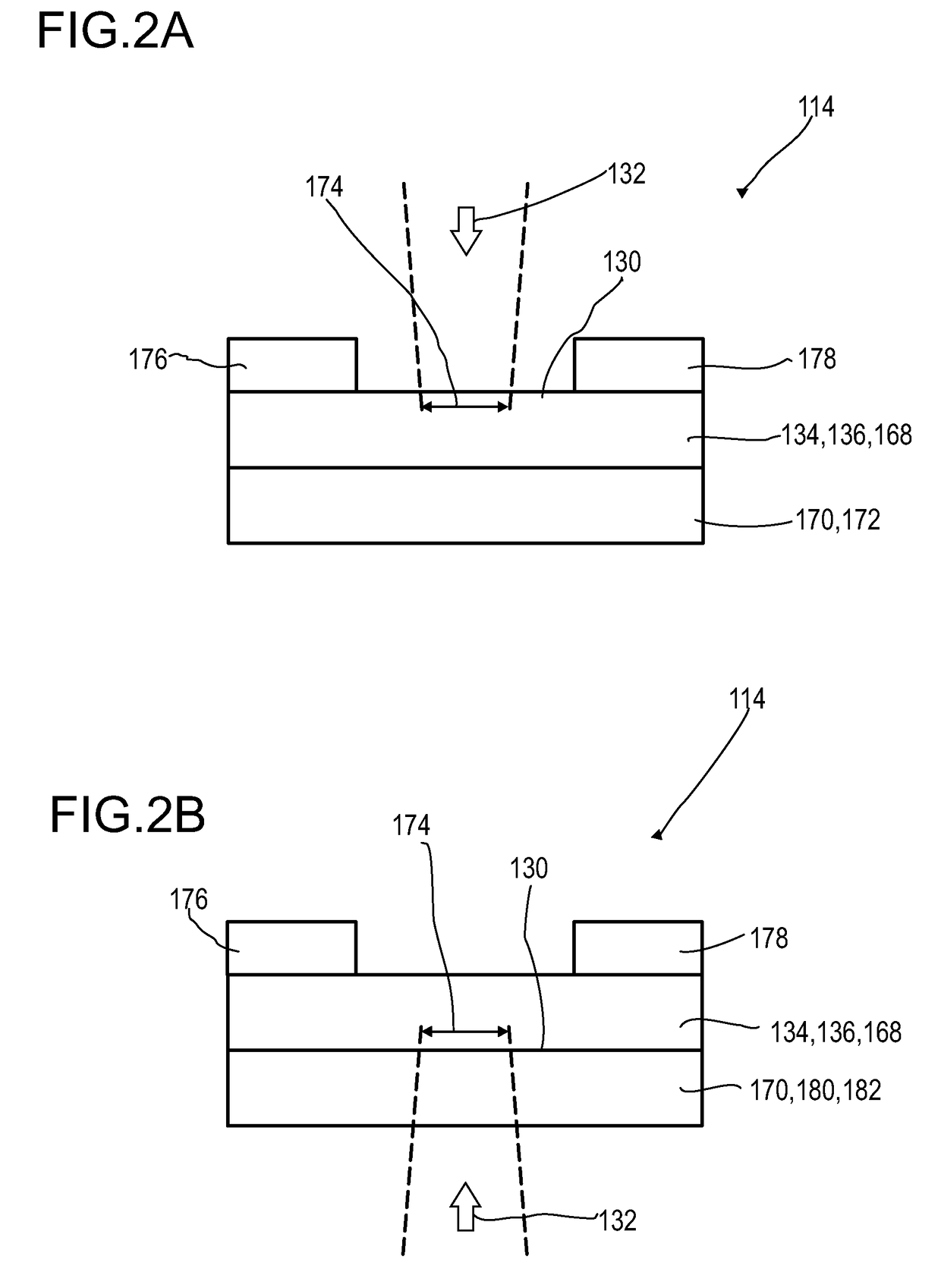
[0121]Using a layer of the organic photoconductive materials exhibits a number of advantages, in particular with respect to the known inorganic photoconductive materials. The layer of the organic photoconductive materials may, preferably, be produced by known high-throughput methods, in particular by a deposition method, preferably a coating method, more preferred a spin-coating method, a slot-coating method, or a blade-coating method, or, alternatively, by evaporation. By this kind of process a transparent, semitransparent or translucent layer may easily be obtained which may exhibit a thickness from 100 μm to 2000 μm, in particular from 200μm to 750 μm. The transparency, semitransparency or translucency of the organic photoconductive materials as obtained in this manner, thus, allows providing a stack of longitudinal sensors which each comprises a layer of this kind of materials. As will be explained below in more detail, the optical detector according to the present invention, however, differs in a particular respect to the known IR detectors in which a chalcogenide photoconductive material, such as lead sulfide (PbS), lead selenide (PbSe), mercury cadmium telluride (HgCdTe; also abbreviated to ‘MCT’), or mercury zinc telluride (HgZnTe; also abbreviated to ‘MZT’), has already been employed. Whereas in an IR detector according to the state of the art, it is essential for various reasons, such as to obtain an excellent signal quality, in particular, in order to achieve a high signal-to-noise ratio under often difficult measurement conditions, to illuminate the sensor region, which may comprise one or more of the mentioned or other chalcogenide photoconductive materials, as far as possible. From this point of view, it would be considered as completely deceptive even to contemplate reducing the cross-section of a light beam which may impinge on the sensor region. In the known art of IR detectors, it is rather best practice to completely illuminate the sensor region; any deviation therefrom would be considered as an erroneous experimental set-up.
[0122]In contrast with this long-known conception according to the state of the art, it may, nevertheless, be particularly advantageous to, still, vary the cross-section of a light beam which may impinge onto the sensor region that comprises a photoconductive material, preferably, one or more photoconductive material as described above and / or below in more detail. By evaluating the longitudinal sensor signal of the longitudinal optical sensor in an evaluation device it may, thus, in a rather surprising manner by employing this specific combination, be possible to generate at least one item of information on a longitudinal position, such as a depth, of the object which may, previously, have emitted and / or reflected the light beam which, thereafter, may have impinged onto the sensor region of the optical detector. Consequently, using an appropriate photoconductive material in combination with a variation of the cross-section of an incident light beam impinging on this photoconductive material and the application of a specifically adapted evaluation device may, thus, open extended measurement options which have not been possible so far.

Problems solved by technology

These distance measurements, however, imply the use of a plurality of sensors, the use of moving parts and, thus, make use of a rather complex and voluminous optical setup.
Thus, a rather voluminous and complex system is proposed, the miniaturization of which is rather challenging.
Further, again, moving parts are used which further increase the complexity of the system.

Method used


Image

  • Detector for an optical detection of at least one object
  • Detector for an optical detection of at least one object
  • Detector for an optical detection of at least one object

Examples


Embodiment Construction

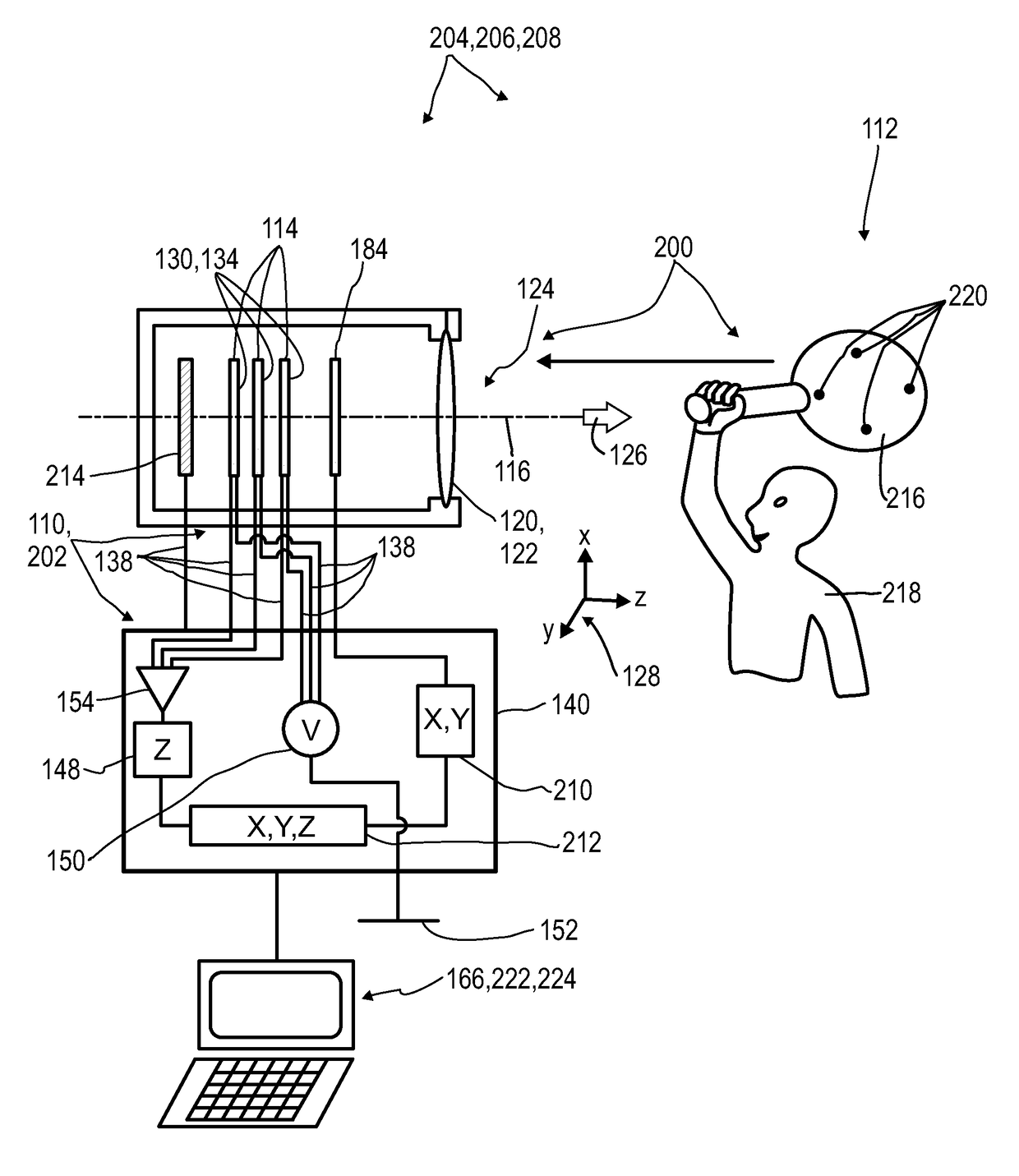
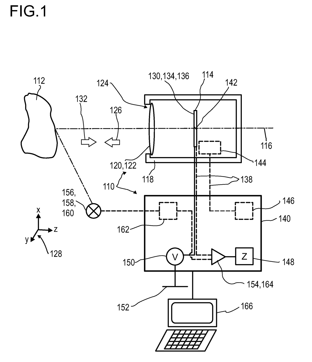
[0554]FIG. 1 illustrates, in a highly schematic fashion, an exemplary embodiment of an optical detector 110 according to the present invention, for determining a position of at least one object 112. The optical detector 110 may preferably be adapted to be used as an infrared detector. However, other embodiments are feasible. The optical detector 110 comprises at least one longitudinal optical sensor 114, which, in this particular embodiment, is arranged along an optical axis 116 of the detector 110. Specifically, the optical axis 116 may be an axis of symmetry and / or rotation of the setup of the optical sensors 114. The optical sensors 114 may be located inside a housing 118 of the detector 110. Further, at least one transfer device 120 may be comprised, preferably a refractive lens 122. An opening 124 in the housing 118, which may, particularly, be located concentrically with regard to the optical axis 116, preferably defines a direction of view 126 of the detector 110. A coordinat...


PUM


Abstract

Disclosed herein is a detector (110) containing: at least one longitudinal optical sensor (114), wherein the longitudinal optical sensor (114); and at least one evaluation device (140), wherein the evaluation device (140) is designed to generate at least one item of information on a longitudinal position of the object (112) by evaluating the longitudinal sensor signal of the longitudinal optical sensor (114). Also disclosed herein are articles containing the detector (110), and methods for optical detection of objects using the detector (110).

Description

DESCRIPTIONField of the Invention[0001]The invention relates to a detector for an optical detection of at least one object, in particular, for determining a position of at least one object, specifically with regard to a depth or both to the depth and a width of the at least one object. Furthermore, the invention relates to a human-machine interface, an entertainment device, a scanning system, a tracking system, a stereo-scopic system; and a camera. Further, the invention relates to a method for optical detection of at least one object and to various uses of the detector. Such devices, methods and uses can be employed for example in various areas of daily life, gaming, traffic technology, mapping of spaces, production technology, security technology, medical technology or in the sciences. However, further applications are possible.Prior art[0002]Various detectors for optically detecting at least one object are known on the basis of optical sensors. WO 2012 / 110924 A1 discloses a detec...

Claims


Application Information

Patent Timeline
Patent Type & Authority Applications(United States)
IPC IPC(8): G01S17/66H01L31/09G01S7/481A63F13/213A63F13/655A63F13/30H01L51/42G01S17/06
CPCG01S17/66G01S7/4816G01S17/06H01L31/09H01L51/4253A63F13/213A63F13/655A63F13/30H01L27/14601H01L27/14665H10K39/32H10K85/113H01L31/0224Y02E10/549H10K30/30
Inventor VALOUCH, SEBASTIANBRUDER, INGMARSEND, ROBERTLUNGENSCHMIED, CHRISTOPHHERMES, WILFRIEDTHIEL, ERWINIRLE, STEPHAN
Owner TRINAMIX GMBH
Why Eureka
Try Eureka