Small-diameter snare

a small diameter, snare technology, applied in the field of surgical snares, can solve the problem of losing temporary access to the site within the patient, and achieve the effect of increasing the ability to ensnare and capture objects, reducing the diameter or cross section, and maximizing the support to the body portion

Inactive Publication Date: 2005-10-20
VASCULAR SOLUTIONS
View PDF28 Cites 72 Cited by
  • Summary
  • Abstract
  • Description
  • Claims
  • Application Information

AI Technical Summary

Benefits of technology

[0008] This invention overcomes prior disadvantages by providing a small-diameter snare device consisting of a hollow, elongate, thin-walled polymer outer sheath. A single central core wire extends through the entire length of the sheath. The outer diameter of the core wire is sized close to the inner diameter of the sheath while allowing for axial sliding, in order to maximize the support to the body portion of the snare device. The distal end of the core wire has a tapered section of reduced diameter or cross section to provide a “guidewire-like” flexibility to the distal portion of the device. A second wire of about fifty percent of the inner diameter of the sheath is shaped to form a snare loop and the two ends are attached to the distal most portion of the central core wire via welding, soldering, or brazing. After assembly of the core and sheath, a second short, hollow tube is fitted over the proximal end of the central core and attached thereto to provide an actuating handle to slideably move the central core within the sheath, thus exposing and retracting the snare loop from the open distal end of the sheath. The loop is typically circular or oval shaped and can also be multiplanar (for example, a twisted, figure eight shape) so as to increase the ability to ensnare and capture objects. The loop attachment to the core wire is facilitated and strengthened by a wrapped coupling coil formed typically of 0.001-inch platinum wire applied to secure the loop prior to soldering (brazing or other metal-flowing joining techniques), and through which solder flows to permanently secure the loop to the core wire.

Problems solved by technology

Alternatively, the snare may be passed through the guiding catheter along side of the balloon or access catheter without the need to remove the prior device, and thus, lose temporary access to the site within the patient.

Method used


Image

  • Small-diameter snare
  • Small-diameter snare
  • Small-diameter snare

Examples


Embodiment Construction

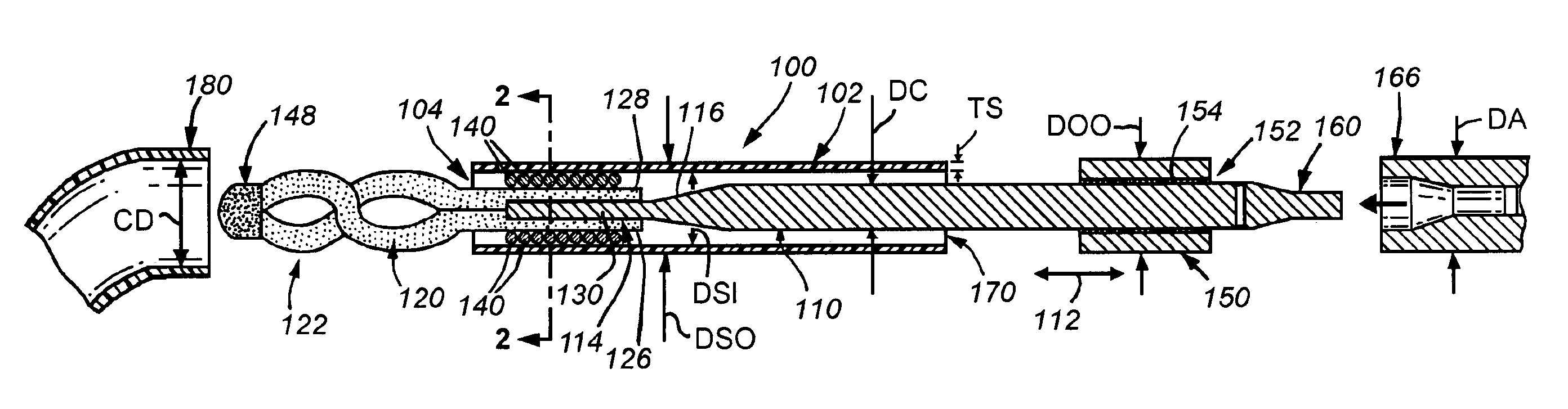
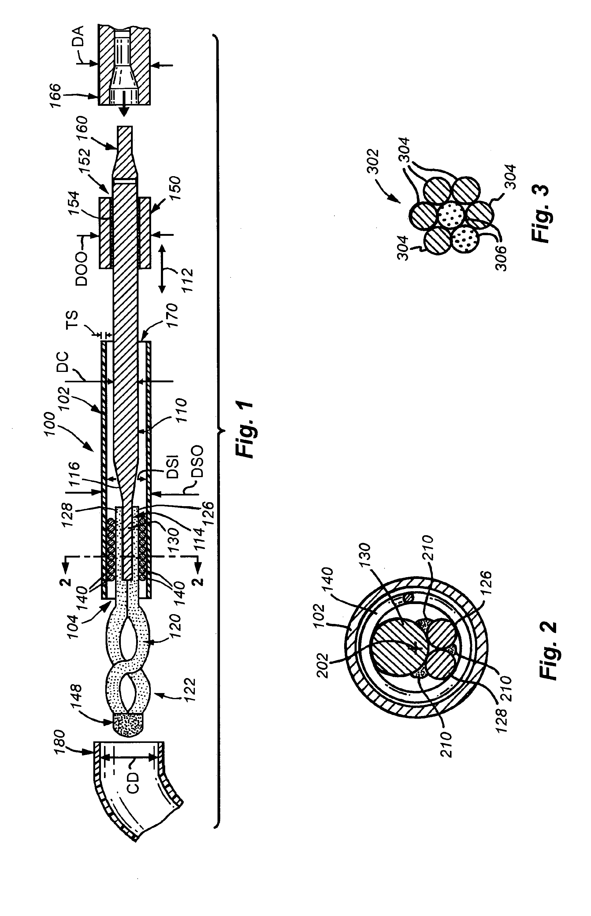
[0018]FIG. 1 shows a small diameter snare device 100 according to an embodiment of this invention. The device 100 includes of a hollow, elongate, thin-walled polymer outer sheath 102. The sheath 102 may include a radiopaque marker located at or adjacent to the open distal end 104 for visualization under fluoroscopy. The polymer can be any one of a number of acceptable biocompatible polymers with sufficient structural strength to support a thin-walled (approximately 0.0020 inch maximum wall thickness TS) structure without rupture or other failure under normal use conditions.

[0019] In one embodiment, the sheath is constructed from polyimide with a tungsten filler for radiopacity. The radiopaque filler may be added to the sheath polymer during processing, or a radiopaque material may be added to the outer surface via vapor deposition, plating, ion implantation processes, or the like. Alternatively, radiopaque markers can be applied at the distal end and / or other known locations along ...


PUM


Abstract

This invention provides a small diameter snare device consisting of a hollow, elongate, thin-walled polymer outer sheath. A single central core wire extends through the entire length of the sheath. The outer diameter of the core wire is sized close to the inner diameter of the sheath while allowing for axial sliding, in order to maximize the support to the body portion of the snare device. The distal end of the core wire has a tapered section of reduced diameter or cross section to provide a “guidewire-like” flexibility to the distal portion of the device. A second wire of about fifty percent of the inner diameter of the sheath is shaped to form a snare loop and the two ends are attached to the distal most portion of the central core wire via welding, soldering, or brazing. After assembly of the core and sheath, a second short, hollow tube is fitted over the proximal end of the central core and attached thereto to provide an actuating handle to slideably move the central core within the sheath, thus exposing and retracting the snare loop from the open distal end of the sheath. The loop is typically circular or oval shaped and can also be multiplanar (for example, a twisted, figure eight shape) so as to increase the ability to ensnare and capture objects. The loop attachment to the core wire is facilitated and strengthened by a wrapped coupling coil formed typically of 0.001-inch platinum wire applied to secure the loop prior to soldering (brazing or other metal-flowing joining techniques), and through which solder flows to permanently secure the loop to the core wire.

Description

CROSS-REFERENCE TO RELATED APPLICATION [0001] The present application claims the benefit of U.S. Provisional Patent Application Ser. No. 60 / 551,313, which was filed on Mar. 8, 2004, by Richard M. DeMello et al., for a SMALL-DIAMETER SNARE and is hereby incorporated by reference.BACKGROUND OF THE INVENTION [0002] 1. Field of the Invention [0003] The present invention relates to surgical snares, and more particularly to devices for retrieving broken, dislodged, or separated medical devices from within the vascular system. [0004] 2. Background Information [0005] Certain snare devices have become available over recent years for retrieving malfunctioning or misplaced devices within the cardiovascular and non-vascular regions of the body. These typically consist of fairly large diameter sheaths, which house a movable central wire or wires whose distal ends are formed into a loop or loops. The loop is used to ensnare and capture the desired object for withdrawal and removal from the body. ...

Claims


Application Information

Patent Timeline
Patent Type & Authority Applications(United States)
IPC IPC(8): A61B17/22A61B17/24A61B17/28A61B17/32A61B19/00
CPCA61B17/221A61B17/32056A61B19/54A61B2017/2924A61B2017/22042A61B2017/22045A61B2017/2212A61B2017/22035A61B90/39
Inventor DEMELLO, RICHARD M.FINLAYSON, MAUREEN A.FLIGHT, BRUCE W.BURKHARDT, JON
Owner VASCULAR SOLUTIONS
Why Eureka
Try Eureka