Arrangement in a supporting device for goods

a technology for supporting devices and goods, which is applied in the direction of show hangers, show shelves, show stands, etc., can solve the problems of unintentional backward movement of the support device in the compartment, increased difficulty in intentional movement of the support device, and increased complexity of the device. , to achieve the effect of simple us

Inactive Publication Date: 2003-08-14
HL DISPLAY
View PDF0 Cites 93 Cited by
  • Summary
  • Abstract
  • Description
  • Claims
  • Application Information

AI Technical Summary

Benefits of technology

[0014] This operating tool can thus always remain in place and is simple to use and can be so designed that it automatically raises up the bottom plate, along with the goods standing on the bottom plate, when it is pulled forward. When the movement of the support device has been completed, the operating tool can be pushed right back into the compartment, whereupon the support device returns to the initial position with the locking elements engaging with the sawtooth racks on the track.

Problems solved by technology

A problem with certain known devices of this kind has been that the support device can be moved backward in the compartment unintentionally by the application of a force to the vertical support back.
This has, however, meant that the devices have become more complicated to use, as an intentional movement of the support device has also been made more difficult.
As the spring element is located at the back of the support device, there must be room to reach beside or above the support device, which is not always the case.
In many cases, this can be difficult to carry out, as there can be no room to reach behind the support device due to the positions of the shelf above and the side dividers.
It cannot, however, be left in place, as it would then protrude out from the shelf.

Method used


Image

  • Arrangement in a supporting device for goods
  • Arrangement in a supporting device for goods
  • Arrangement in a supporting device for goods

Examples


Embodiment Construction

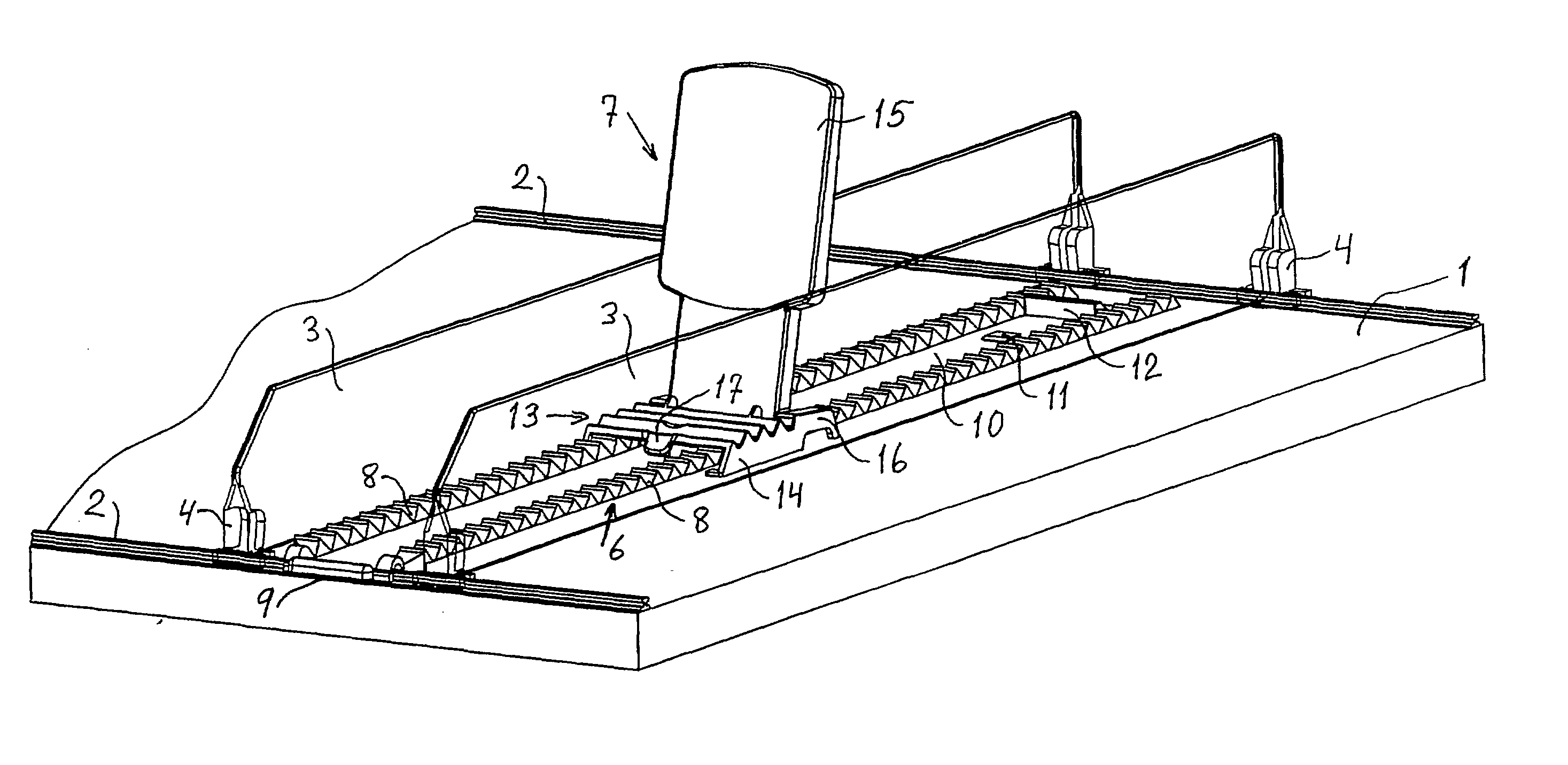
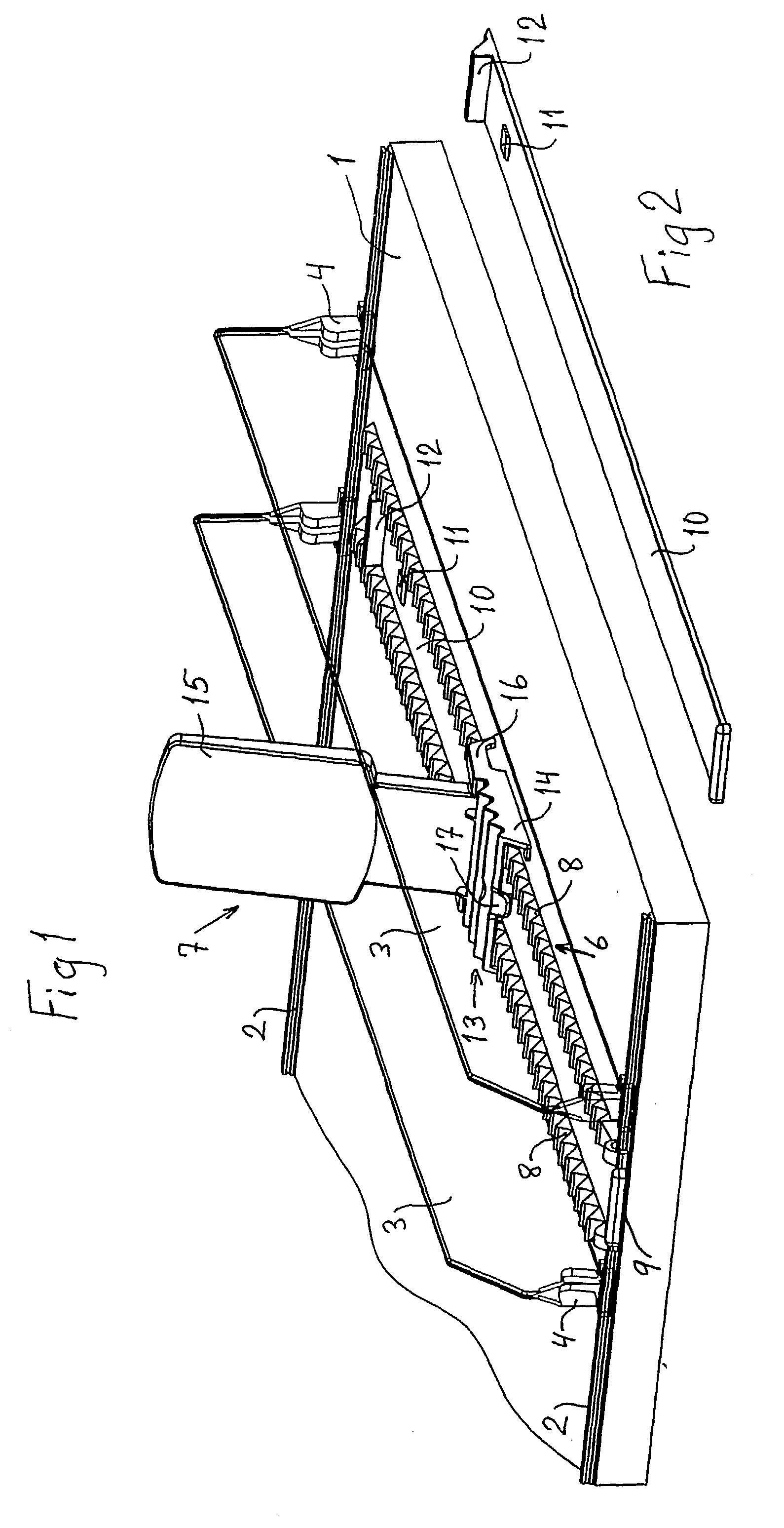
[0025] FIG. 1 shows a part 1 of a shop shelf with fixing strips 2 running along the front and back edges of the shelf. Dividers 3 with essentially U-shaped fixing heads 4 are snapped onto the fixing strips 2, so that these dividers can be moved along the shelf to form compartments of the required width. In the figure only one compartment is shown.

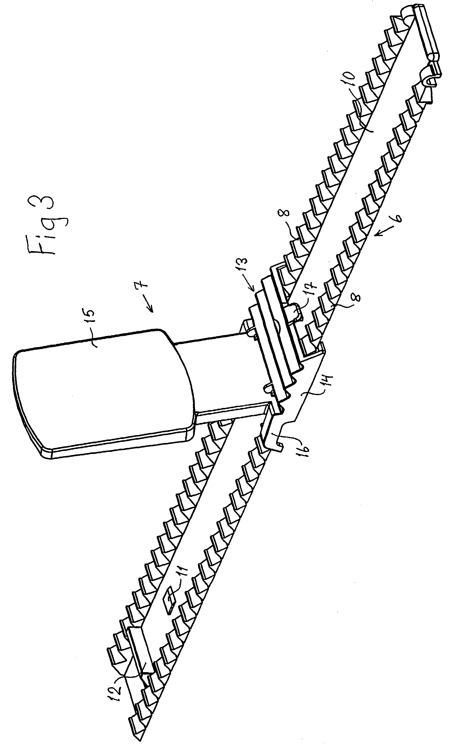
[0026] At the bottom of the compartment, there is a track 6 for a support device 7. The ends of this track can also be snapped onto the fixing strips 2.

[0027] The track 6 has two side portions provided with transverse sawtooth racks 8. Between these portions there is a recess 9. The sawtooth racks 8 comprise essentially V-shaped troughs with crests between.

[0028] FIG. 2 shows an elongated operating tool 10 with two projecting lugs 11, 12 on the rear part. The operating tool 10 is relatively thin and is designed to be inserted into the recess 9 in the support track 6 in such a way that it can be moved, so that it extends underneath the suppo...


PUM


Abstract

The device for use with a support for goods which are to stand in rows on the shelves of a shop or store-room, in particular such goods as are arranged in compartments formed by transverse dividers. The support comprises a track (6) provided with sawtooth racks (8) and a support device (7) that can be moved along the track, with a bottom plate (13), a suport back (15) projecting upward from the bottom plate, and backward-projecting locking elements (16) which interact with the sawtooth rack (8) in the track. The device comprises an operating tool (10) arranged under the bottom plate (13) of the support device (7) in such a way that it can be pulled out. The operating tool is designed with lugs projecting upward from it arranged to interact with the bottom plate (13) of the support device when the opeating tool (10) is pulled out, in order to bring the support device forward by means of a forward movement of the operating tool, for moving forward goods which are supported by the support device.

Description

[0001] The present invention relates to a device for use with a support for goods which are to stand in rows on the shelves of a shop or store-room, in particular such goods as are arranged in compartments formed by transverse dividers, which support comprises a track provided with sawtooth racks and a support device that can be moved along the track, which support device has a bottom plate and a support back projecting upward from the bottom plate.BACKGROUND TO THE INVENTION[0002] Supports of this kind are used, for example, for supporting products packed in sachets, small boxes or packages. In order to make it easy for the consumer to take hold of the first package in a row, the row of packages should be kept to the front edge of the shelf. This requires among other things the row of packages to be supported by a support back which can easily be moved in the appropriate compartment. The support is moved forward as the goods are removed, but must then be able to be returned to a po...

Claims


Application Information

Patent Timeline
Patent Type & Authority Applications(United States)
IPC IPC(8): A47F1/12A47F5/00
CPCA47F5/005A47F1/12
Inventor LINDEN, HENRIKJOSEFSSON, B?OUML, RJE
Owner HL DISPLAY
Why Eureka
Try Eureka