
Vibration pickup comprising a pressure sleeve

a pressure sleeve and vibration pickup technology, which is applied in the direction of instruments, rapid change measurement, measurement apparatus components, etc., can solve the problem of making the optimal introduction of vibrations to the actual sensor arrangement via the pressure sleeve more difficul

Inactive Publication Date: 2003-08-21
ROBERT BOSCH GMBH
View PDF5 Cites 1 Cited by
  • Summary
  • Abstract
  • Description
  • Claims
  • Application Information

AI Technical Summary

Problems solved by technology

Since compensation for this cavity by elastic deformation of the relatively rigid sensor components is generally minimal, an optimal introduction of the vibrations to the actual sensor arrangement via the pressure sleeve is made more difficult.

Method used


Image

  • Vibration pickup comprising a pressure sleeve
  • Vibration pickup comprising a pressure sleeve

Examples


Embodiment Construction

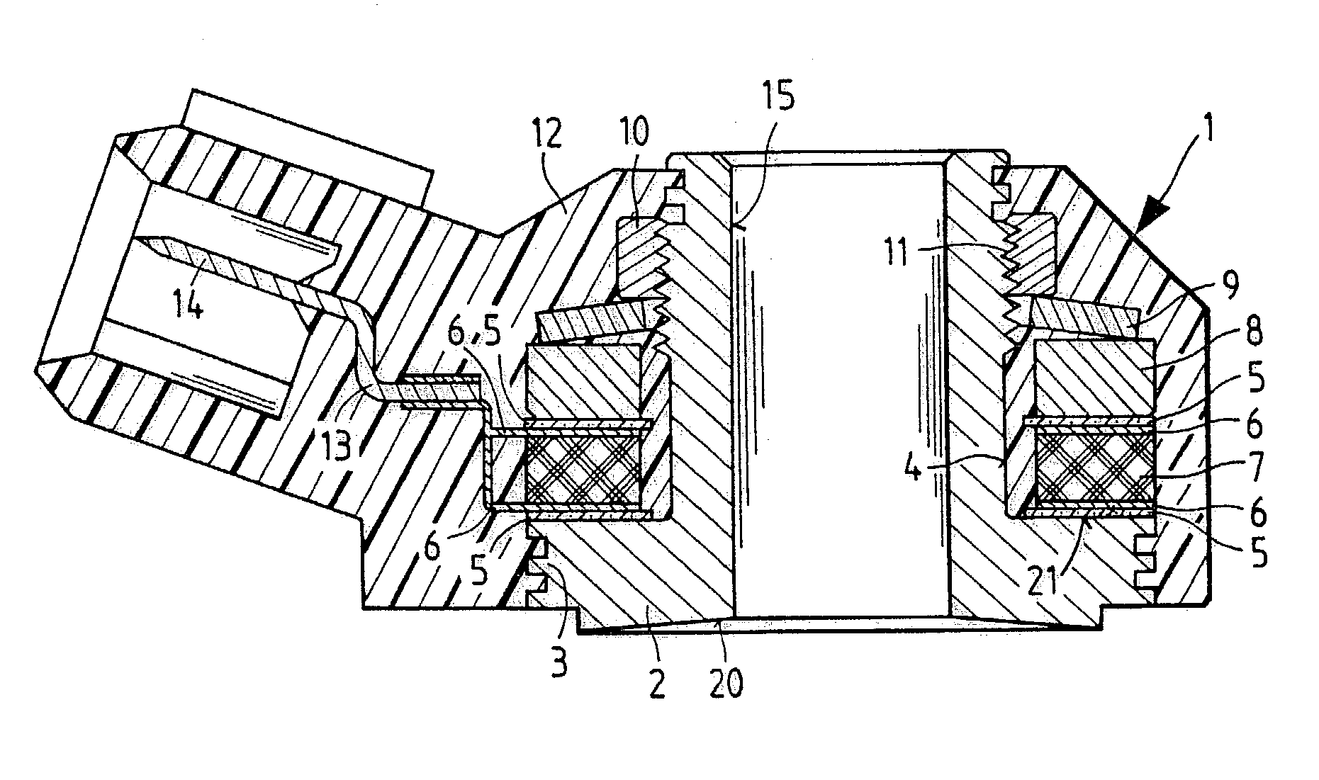
[0014] FIG. 1 shows a knock sensor as a vibration meter for an internal combustion engine, having an outer plastic housing 1 in which a pressure sleeve 2 is disposed. In its lower end region, pressure sleeve 2 has a flange-type collar 3 by which it rests with its lower bottom surface 20 on the engine block (not shown) whose vibrations are to be detected.

[0015] At outer circumference 4 of pressure sleeve 2, beginning at a lower bearing surface 21 at flange-type collar 3, the following components are disposed: An insulating disk 5, a first contact disk 6, a piezoceramic disk 7 as the actual sensor element, and above it, another second contact disk 6 as well as a second insulating disk 5. A seismic mass 8, which is pressed in the direction of piezoceramic disk 7 by an annular spring 9, is placed on top of this arrangement. Spring 9 is prestressed by a ring nut 10, which is screwed onto an outer thread 11 at the upper part of pressure sleeve 2.

[0016] In an integrated connector 12 of hou...


PUM


Abstract

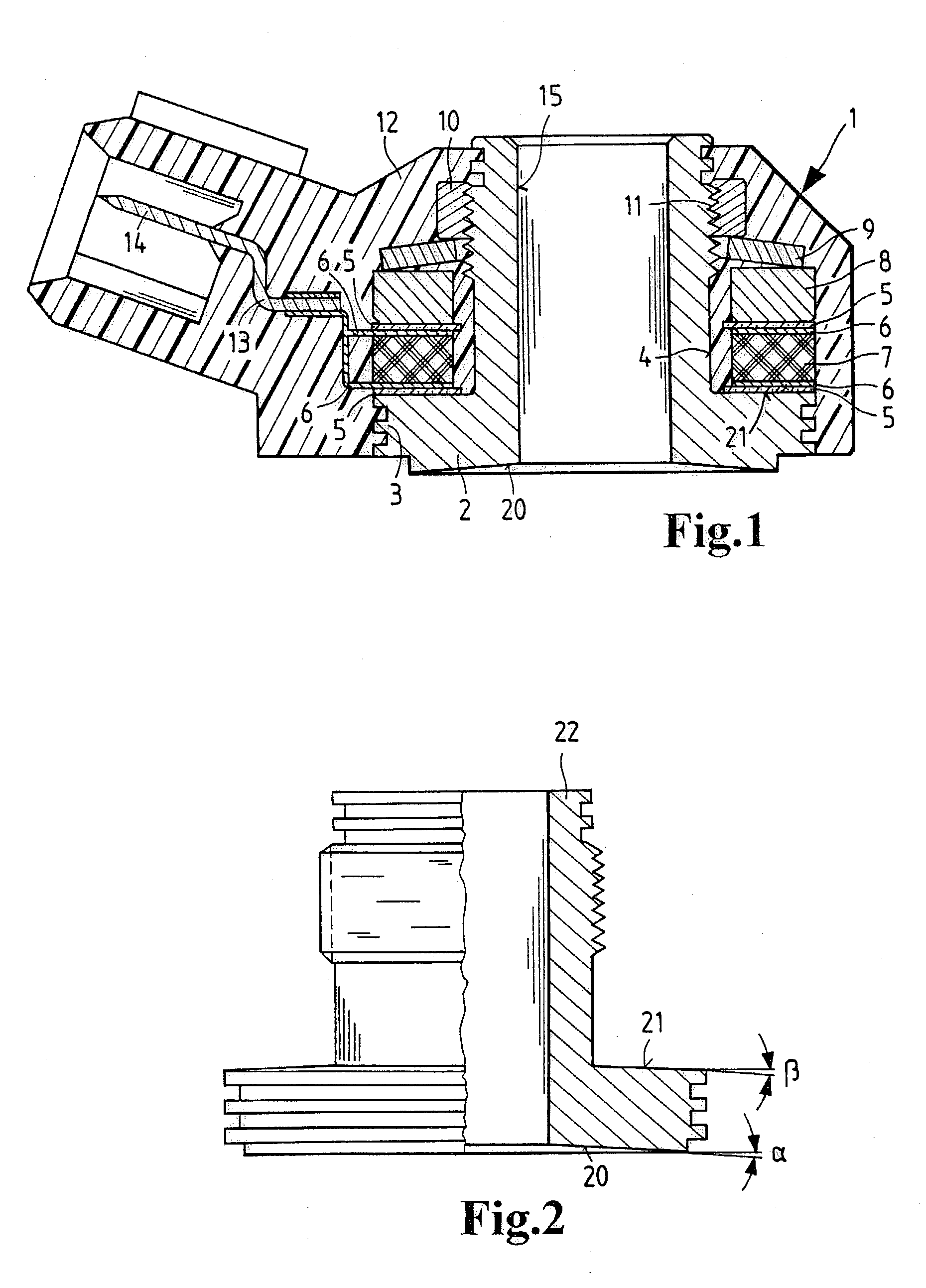
A vibration meter having a pressure sleeve is proposed, in which the pressure sleeve (2, 22) may be mounted under pressure at a bottom surface (20) on a component causing vibrations, and the bottom surface (20) has a contour, prior to mounting, which runs radially inward in a concave manner. Furthermore, prior to mounting, the bearing surface (21) has a contour, which runs radially inward in a concave manner, the contour being dimensioned such that, after the mounting, at least one sensor arrangement (7, 5, 6, 8) lies substantially flat on the bearing surface (21) on the inside of the pressure sleeve (22).

Description

BACKGROUND INFORMATION[0001] The present relation is directed to a vibration meter having a pressure sleeve according to the species defined in the main claim.[0002] German Patent 44 03 660 A1 already describes a vibration meter having a pressure sleeve which is used as a knock sensor for monitoring the function of an internal combustion engine in a motor vehicle. This pressure sleeve is fixedly mounted via a bearing surface on the component causing the vibrations, in this case to the engine block of the internal combustion engine.[0003] With this known arrangement, the vibrations to be detected are knocking sounds of the internal combustion engine during operation, the sounds being transmitted via the pressure sleeve to a piezoceramic disk as the actual sensor element, which has interposed contact disks and insulating disks allowing the signal pick-up, and in this manner generates an analyzable output signal.[0004] The manner of mounting or clamping of this sensor arrangement on th...

Claims


Application Information

Patent Timeline
IPC IPC(8): G01H11/08G01L23/22
CPCG01L23/222G01H11/08G01D11/245
Inventor BRAMMER, HARTMUT
Owner ROBERT BOSCH GMBH
Learn More