Discharge lamp lighting device and system comprising it

a technology of lighting device and discharge lamp, which is applied in the direction of electric variable regulation, process and machine control, instruments, etc., can solve the problems of unstable discharge arc, insufficient prevention method alone, unstable discharge arc, etc., and achieve less arc jumps and less fluctuation in the brightness of the lamp

Inactive Publication Date: 2003-08-28
PANASONIC CORP
View PDF2 Cites 35 Cited by
  • Summary
  • Abstract
  • Description
  • Claims
  • Application Information

AI Technical Summary

Benefits of technology

0009] The present invention aims to solve the above-described problems, and an object thereof is to provide a discharge-lamp lighting device with fewer arc jumps and less fluctuation in brightness of a lamp even when an inexpensive, small and highly efficient la

Problems solved by technology

A problem associated with this type of lamp is that the discharge arc becomes unstable depending on the temperature of the electrode and the condition of the surface of the electrode.
However, this method alone is insufficient to prevent the arc jump since the method does not addresses some problems including: spot formation that is caused by tungsten halide oxide and that have been remarkable in the recent trend of highly

Method used


Image

  • Discharge lamp lighting device and system comprising it
  • Discharge lamp lighting device and system comprising it
  • Discharge lamp lighting device and system comprising it

Examples


first embodiment

[0052] (First Embodiment)

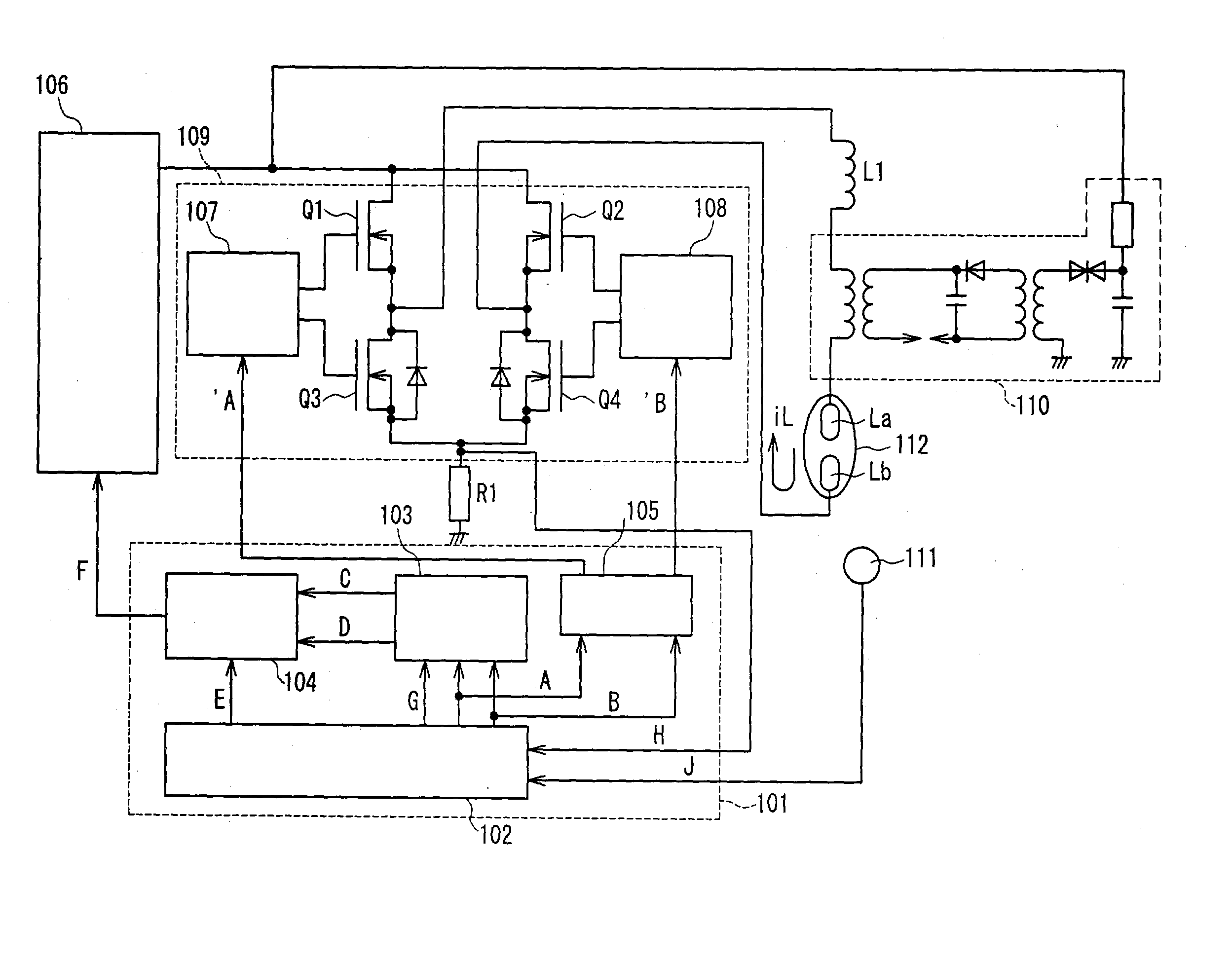
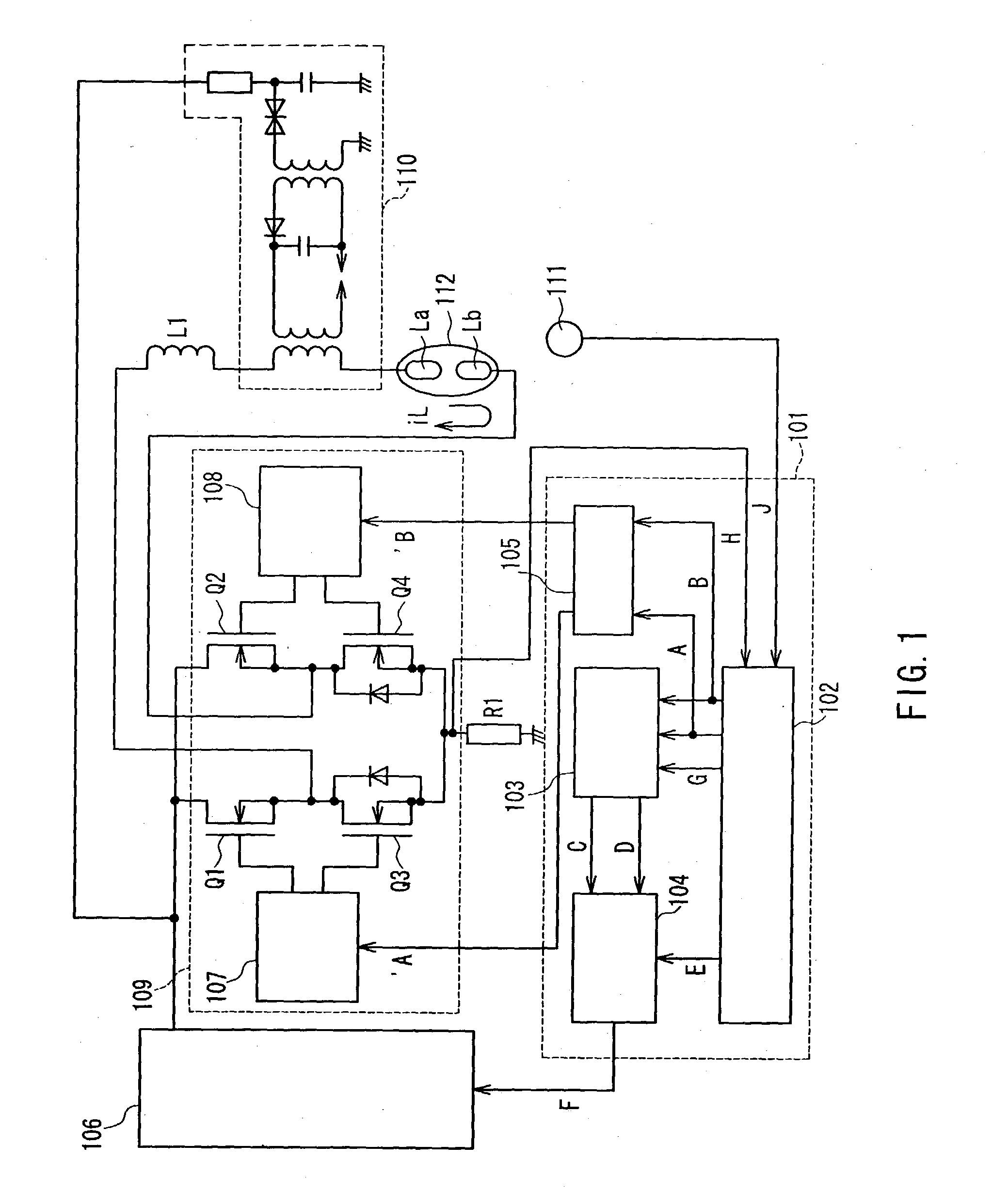
[0053] FIG. 1 is a circuit block diagram showing a structural example of a discharge-lamp lighting device according to a first embodiment of the present invention. The structure shown in FIG. 1 is applied also to each of the following embodiments. The discharge-lamp lighting device is composed of a discharge-lamp controlling portion 101 (controlling portion), a DC-DC converter 106 for outputting a desired current corresponding to a current-controlling signal F from the discharge-lamp controlling portion 101, a commutator 109 for converting a direct current from the DC-DC converter 106 into an alternating current, a high-voltage generating portion 110 for lighting a lamp, a lamp temperature detector or a brightness detector 111, a lamp 112, a current detector (a current detecting resistor) R1 for detecting a current flowing in the lamp 112, and a choke coil L1.

[0054] The commutator 109 is composed of a full-bridge circuit or the like including switching eleme...

second embodiment

[0062] (Second Embodiment)

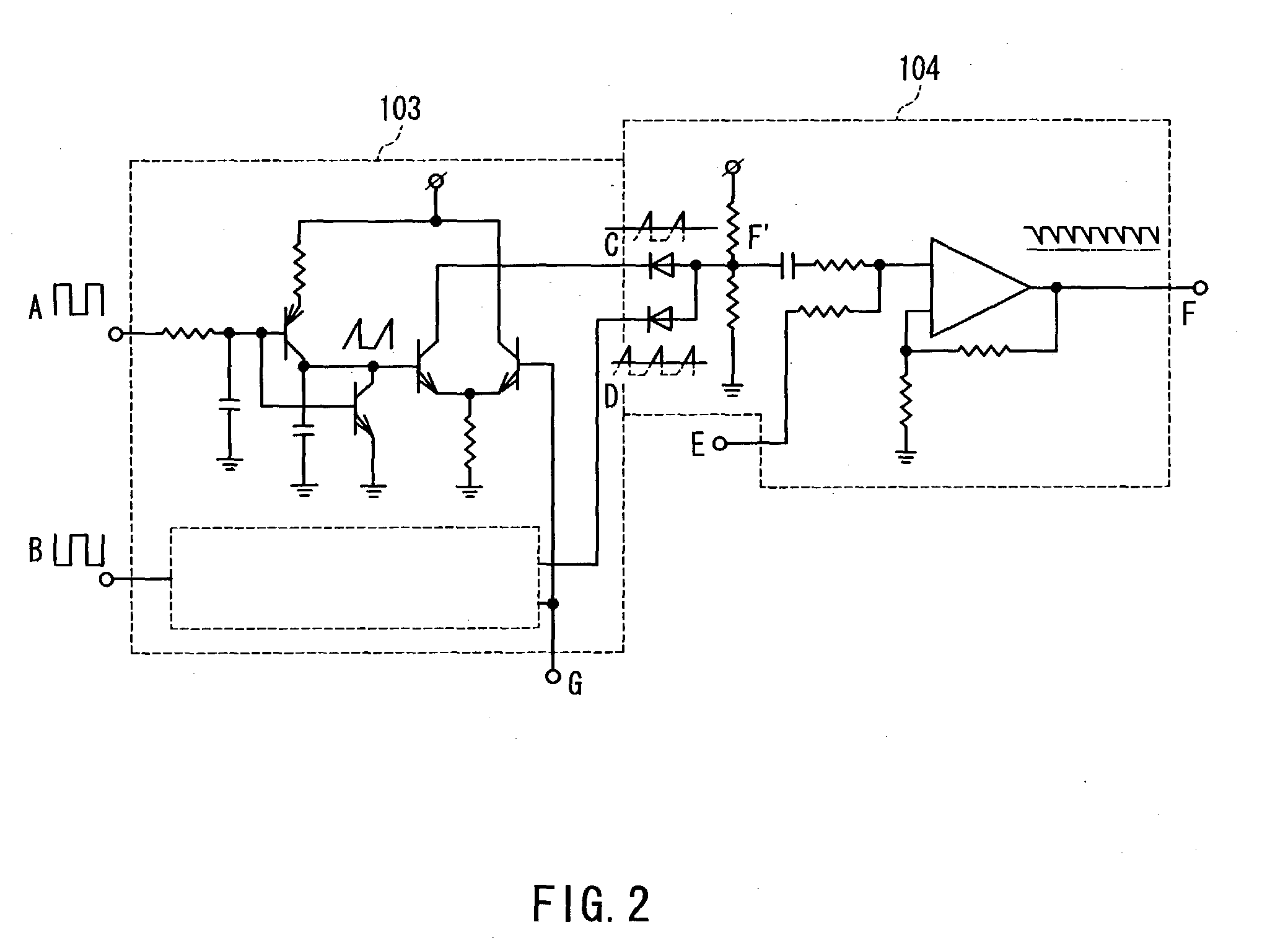
[0063] A second embodiment of the present invention will be described below by referring to FIG. 1 as well. In this embodiment, an amount and timing for superimposing a triangular wave signal onto the current-controlling signal is set variably on the basis of a detected lamp current.

[0064] It has been mentioned in the first embodiment that a superimposition amount / timing adjustment signal G (DC level signal) is inputted from the main controlling portion 102 to the waveform converter 103 so as to adjust the amount and timing of superimposing the triangular wave signal. The lamp current iL commutated at the commutator 109 is detected by the current detector R1, and fed back as a lamp current detection signal H into the main controlling portion 102. At the main controlling portion 102, a superimposition amount / timing adjustment signal G is generated according to the amount of feedback of the lamp current detection signal H, and thus the amount and timing for s...

third embodiment

[0067] (Third Embodiment)

[0068] A third embodiment of the present invention will be described below by referring to FIG. 1 as well. In this embodiment, an amount and timing for superimposing the triangular wave signal onto the current-controlling signal is set variably on the basis of a lamp temperature detected by the lamp temperature detector 111.

[0069] It has been mentioned in the first embodiment that a superimposition amount / timing adjustment signal G (DC level signal) is inputted from the main controlling portion 102 to the waveform converter 103 so as to adjust the amount and timing of superimposing the triangular wave signal. The lamp temperature detected by the lamp temperature detector 111 is fed back as a temperature detection signal J to the main controlling portion 102. At the main controlling portion 102, a superimposition amount / timing adjustment signal G is generated according to a feedback mount of the temperature detection signal J so as to adjust the amount and ti...


PUM


Abstract

A discharge-lamp lighting device is provided which decreases arc jumps, suppresses the fluctuation in brightness of the lamp, and prolongs a life of the lamp, by positively accelerating growth of spots even when an inexpensive, small and highly efficient lamp is used. A discharge-lamp controlling portion (101) sets frequencies of drive-controlling signals (A and B) for drive-controlling a commutator (109) within a predetermined frequency range so that spots formed by arc discharge on electrodes composing a high-pressure discharge lamp grow through a cycle of oxidation-reduction of a metal composing the electrodes, and superimposes a triangular wave signal generated on the basis of the drive-controlling signals onto a current-controlling signal (F) over an entire period of the drive-controlling signals so as to make a peak value of the triangular wave constant, thereby adjusting the waveform of current flowing in the high-pressure discharge lamp.

Description

[0001] The present invention relates to a discharge-lamp lighting device for lighting a discharge lamp such as a metal halide lamp, and a system such as a liquid crystal projector using the discharge-lamp lighting device.[0002] Recently, the brightness of projection-type liquid crystal projectors has been improved dramatically by the use of highly efficient high-pressure discharge lamps (hereinafter, may be abbreviated as `lamp(s)`). However, fluctuation in brightness on a screen, which is caused by a fluctuation of an arc track of a lamp, or a phenomenon called `arc jump`, has been remarkable. A problem associated with this type of lamp is that the discharge arc becomes unstable depending on the temperature of the electrode and the condition of the surface of the electrode. As explained in U.S. Pat. No. 5,608,294, the discharge arc becomes unstable because the origin of the discharge arc jumps to some sharp-pointed projections (hereinafter, referred to as `spot(s)`) formed on the s...

Claims


Application Information

Patent Timeline
IPC IPC(8): H05B41/292
CPCH05B41/2928Y10S315/07Y02B20/208Y02B20/00
Inventor NOGUCHI, TOSHIYUKIKAKIMOTO, YASUHIRO
Owner PANASONIC CORP
Why Eureka
Try Eureka