Zoom lens system, interchangeable lens apparatus and camera system

a technology of interchangeable lenses and zoom lenses, which is applied in the field of zoom lens systems and interchangeable lens apparatuses, can solve the problems of insufficient compensation of various aberrations in close-object in-focus situations, insufficient zoom lenses nor the variable magnification optical system disclosed in the patent documents, and achieves excellent optical performance, less fluctuation in aberrations, and high zoom ratio

Inactive Publication Date: 2013-09-17
PANASONIC CORP
View PDF9 Cites 12 Cited by
  • Summary
  • Abstract
  • Description
  • Claims
  • Application Information

AI Technical Summary

Benefits of technology

[0011]An object of the present invention is to provide: a compact and lightweight zoom lens system having a relatively high zooming ratio, less fluctuation in aberrations associated with focusing, excellent optical performance over the entire focusing function, with sufficiently compensated aberrations particularly in close-object in-focus situations, and excellent blur compensation; and an interchangeable lens apparatus and a camera system each employing the zoom lens system.
[0015]According to the present invention, it is possible to provide: a compact and lightweight zoom lens system having a relatively high zooming ratio, less fluctuation in aberrations associated with focusing, excellent optical performance over the entire focusing function, with sufficiently compensated aberrations particularly in close-object in-focus situations, and excellent blur compensation; and an interchangeable lens apparatus and a camera system each employing the zoom lens system.

Problems solved by technology

In each of the zoom lenses as well as the variable magnification optical system disclosed in the above-described patent documents, since the amount of movement of the lens unit responsible for focusing is determined by the paraxial power configuration in the entire lens system, the amount of fluctuation in aberrations during focusing is not sufficiently compensated from the wide-angle limit to the telephoto limit, and particularly, compensation of various aberrations in a close-object in-focus situation is insufficient.
Further, neither the zoom lenses nor the variable magnification optical system disclosed in the patent documents is capable of performing blur compensation, nor has a blur compensation function that satisfies recent requirements for zoom lens systems.

Method used


Image

  • Zoom lens system, interchangeable lens apparatus and camera system
  • Zoom lens system, interchangeable lens apparatus and camera system
  • Zoom lens system, interchangeable lens apparatus and camera system

Examples


embodiments 1 to 14

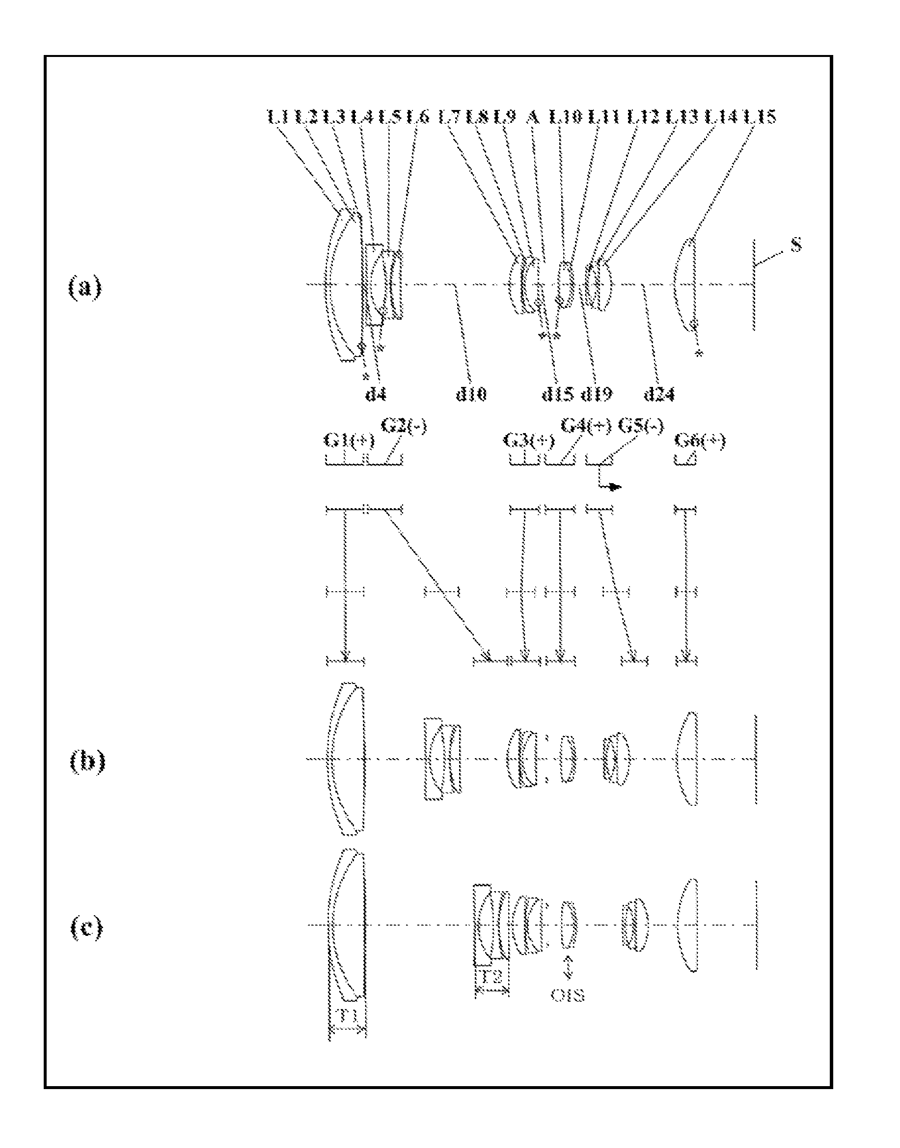
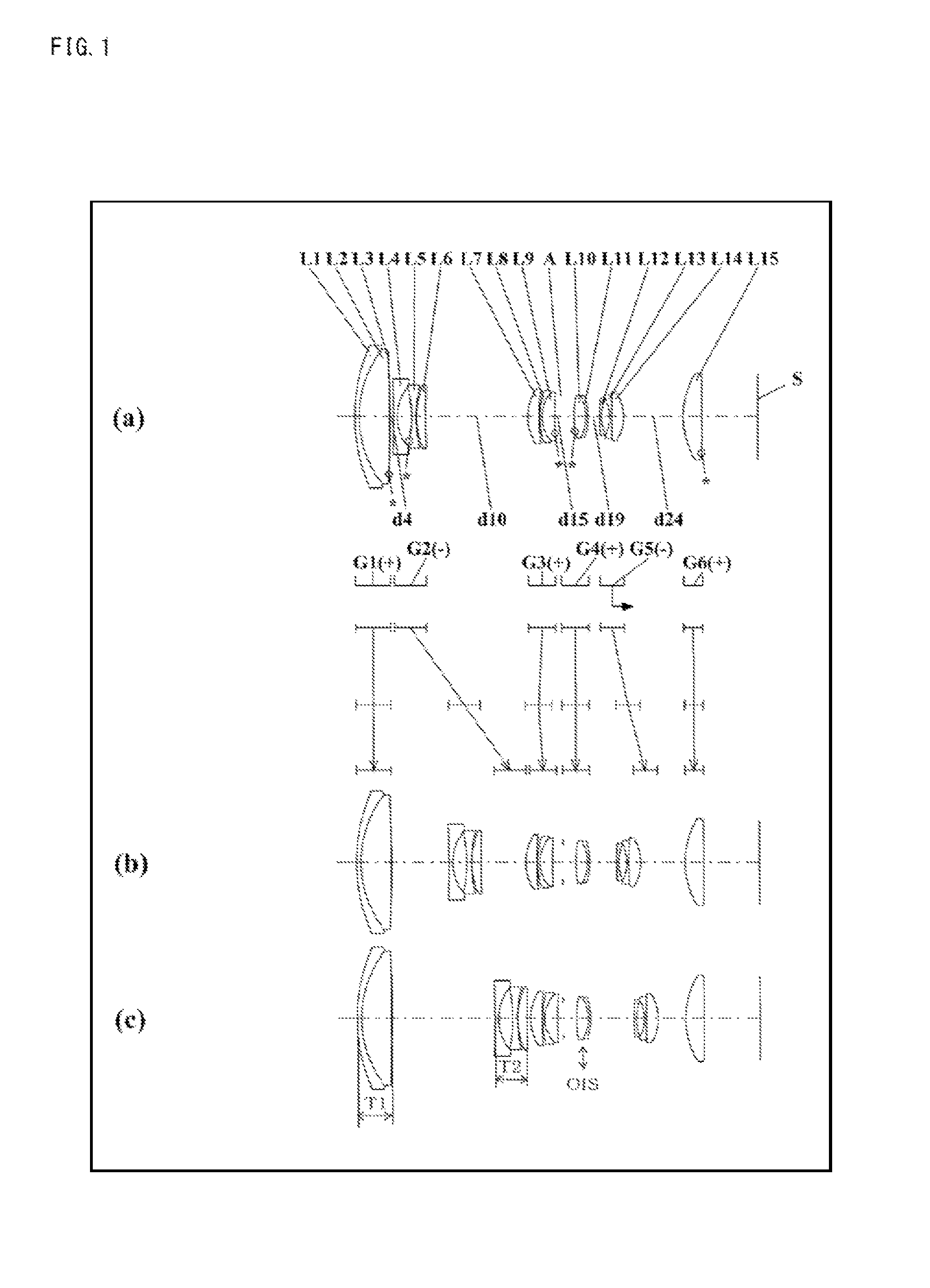
[0074]FIGS. 1, 5, 9, 13, 17, 21, 25, 29, 33, 37, 41, 45, 49, and 53 are lens arrangement diagrams of zoom lens systems according to Embodiments 1 to 14, respectively. Each Fig. shows a zoom lens system in an infinity in-focus situation.

[0075]In each figure, part (a) shows the lens configuration at the wide-angle limit (in the minimum focal length situation: focal length fW), part (b) shows the lens configuration at a middle position (in an intermediate focal length situation: focal length fM=√(fW*fT)), and part (c) shows the lens configuration at the telephoto limit (in the maximum focal length situation: focal length fT). Further, in each figure, the bent arrow located between part (a) and part (b) indicates a line obtained by connecting the positions of each lens unit respectively at the wide-angle limit, a middle position and the telephoto limit, in order from the top. In the part between the wide-angle limit and the middle position, and the part between the middle position and t...

embodiment 15

[0262]FIG. 57 is a schematic construction diagram of an interchangeable-lens type digital camera system according to Embodiment 15.

[0263]The interchangeable-lens type digital camera system 100 according to Embodiment 15 includes a camera body 101, and an interchangeable lens apparatus 201 which is detachably connected to the camera body 101.

[0264]The camera body 101 includes: an image sensor 102 which receives an optical image formed by a zoom lens system 202 of the interchangeable lens apparatus 201, and converts the optical image into an electric image signal; a liquid crystal monitor 103 which displays the image signal obtained by the image sensor 102; and a camera mount section 104. On the other hand, the interchangeable lens apparatus 201 includes: a zoom lens system 202 according to any of Embodiments 1 to 14; a lens barrel 203 which holds the zoom lens system 202; and a lens mount section 204 connected to the camera mount section 104 of the camera body 101. The camera mount s...

example 1 892

mm

Example 2 892 mm


PUM


Abstract

A zoom lens system of lens units, the system including, in object-side-to-image-side order: a first lens unit having positive optical power; a second lens unit; an aperture diaphragm; one or more additional lens units, with a first of the additional lens units being a first focusing-lens unit having negative optical power and moving along the optical axis in the zoom lens system focusing; an image blur compensating lens unit, adjacent the first focusing-lens unit and movable in a direction perpendicular to the optical axis in order to optically compensate image blur; with the lens system satisfying: 0.1<(T1+T2) / H<2.0 (T1 being the axial thickness of the first lens unit, T2 being the axial thickness of the second lens unit, and H being the height of an image the zoom lens system forms on an image surface on the image-side end of the zoom lens system).

Description

CROSS-REFERENCE TO RELATED APPLICATION[0001]This application is based on application No. 2010-187333 filed in Japan on Aug. 24, 2010, the contents of which are hereby incorporated by reference.BACKGROUND OF THE INVENTION[0002]1. Field of the Invention[0003]The present invention relates to a zoom lens system, an interchangeable lens apparatus, and a camera system. In particular, the present invention relates to: a compact and lightweight zoom lens system having a relatively high zooming ratio, less fluctuation in aberrations associated with focusing, excellent optical performance over the entire focusing function, with sufficiently compensated aberrations particularly in close-object in-focus situations, and excellent blur compensation; and an interchangeable lens apparatus and a camera system each employing the zoom lens system.[0004]2. Description of the Background Art[0005]In recent years, interchangeable-lens type digital camera systems (also referred to simply as “camera systems...

Claims


Application Information

Patent Timeline
Patent Type & Authority Patents(United States)
IPC IPC(8): H04N5/262H04N5/228G02B27/64G02B15/14
CPCH04N5/2254G02B15/161G02B15/142G02B15/1461H04N23/55
Inventor IMAOKA, TAKUYAMIYAZAKI, KYOICHI
Owner PANASONIC CORP
Why Eureka
Try Eureka