Discharge lamp lighting device and system comprising it
a technology of lighting device and discharge lamp, which is applied in the direction of electric variable regulation, process and machine control, instruments, etc., can solve the problems of unstable discharge arc, insufficient prevention method alone, unstable discharge arc, etc., and achieve less arc jumps and less fluctuation in the brightness of the lamp
- Summary
- Abstract
- Description
- Claims
- Application Information
AI Technical Summary
Benefits of technology
Problems solved by technology
Method used
Image
Examples
first embodiment
(First Embodiment)
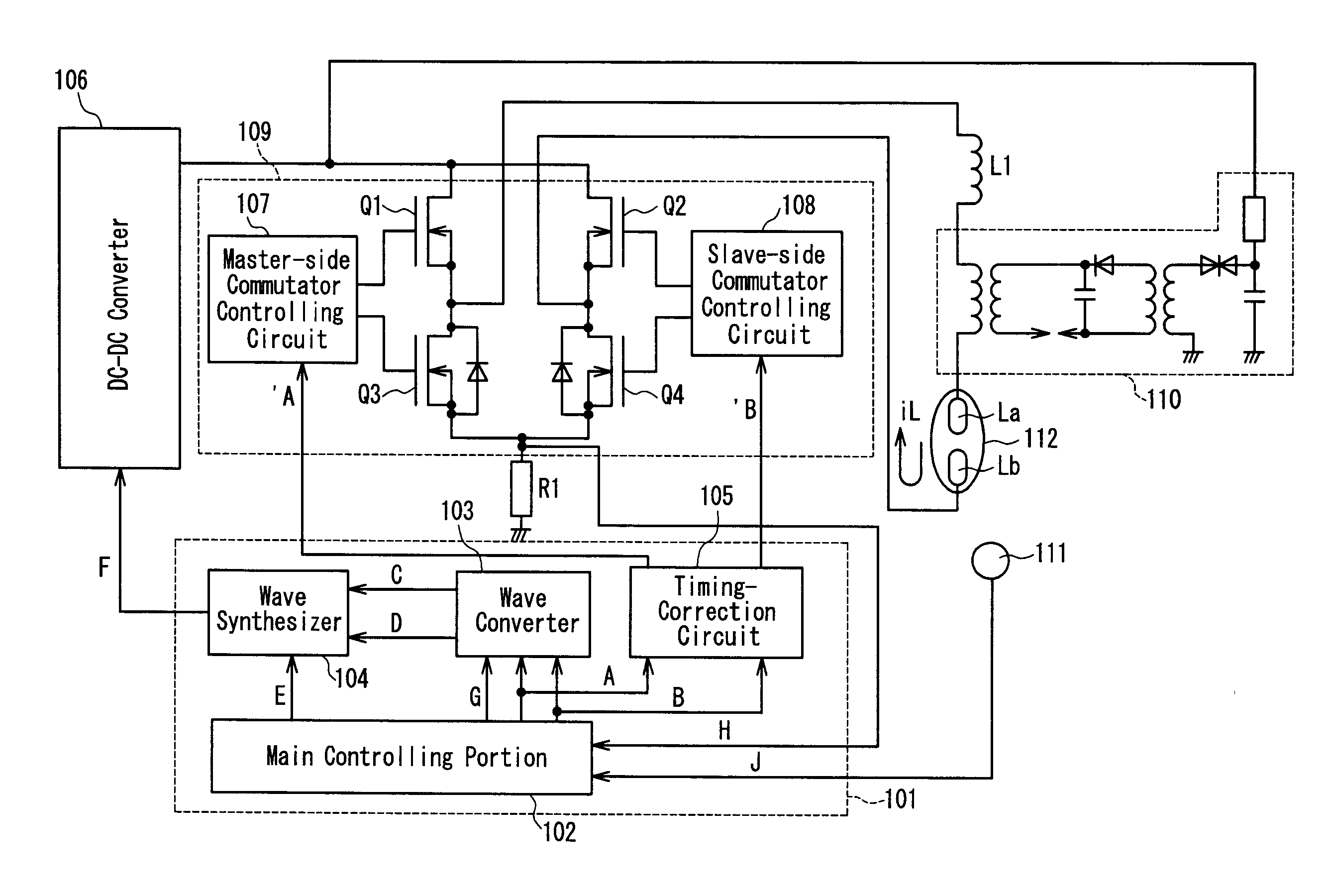
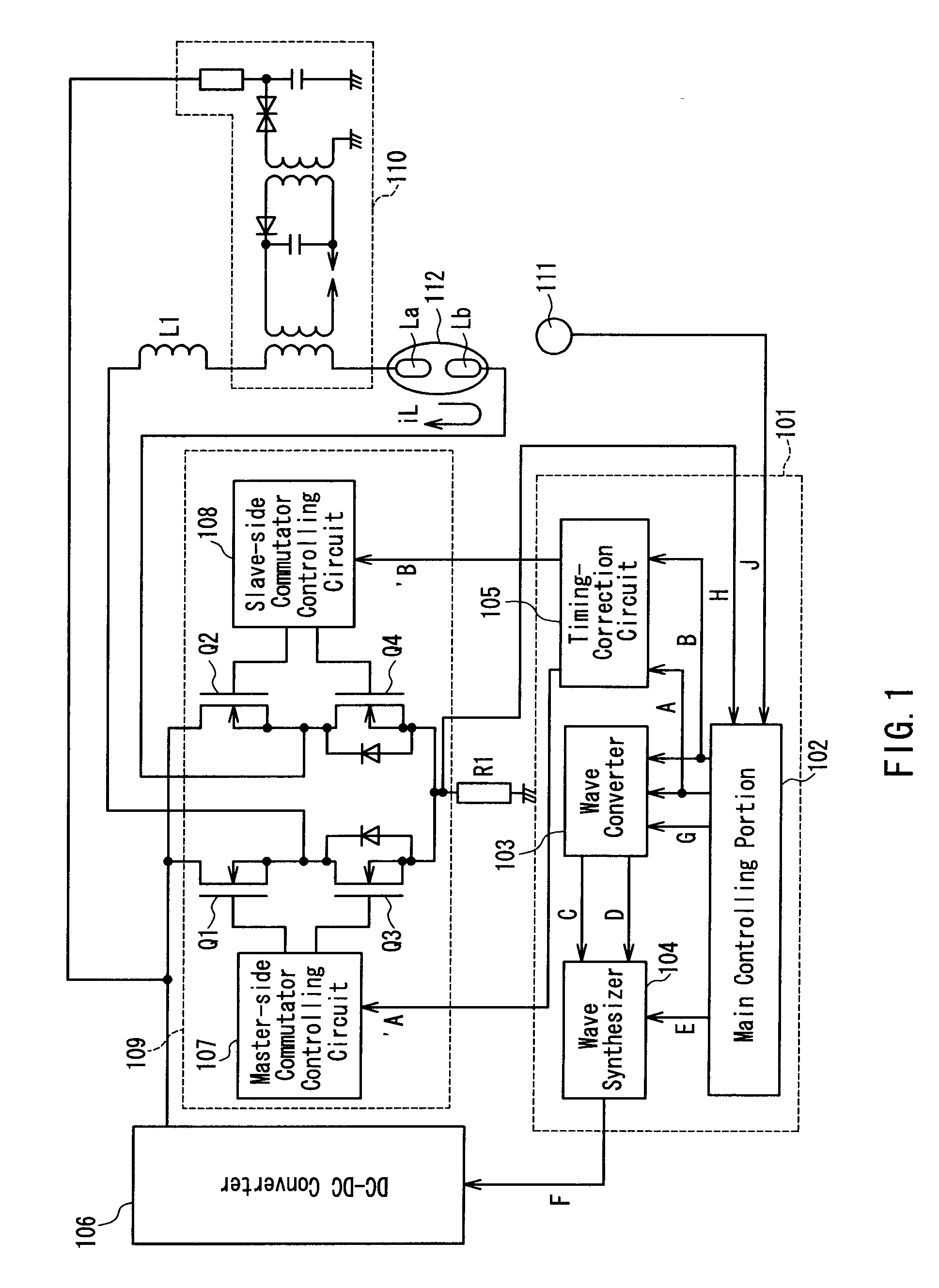
FIG. 1 is a circuit block diagram showing a structural example of a discharge-lamp lighting device according to a first embodiment of the present invention. The structure shown in FIG. 1 is applied also to each of the following embodiments. The discharge-lamp lighting device is composed of a discharge-lamp controlling portion 101 (controlling portion), a DC-DC converter 106 for outputting a desired current corresponding to a current-controlling signal F from the discharge-lamp controlling portion 101, a commutator 109 for converting a direct current from the DC-DC converter 106 into an alternating current, a high-voltage generating portion 110 for lighting a lamp, a lamp temperature detector or a brightness detector 111, a lamp 112, a current detector (a current detecting resistor) R1 for detecting a current flowing in the lamp 112, and a choke coil L1.
The commutator 109 is composed of a full-bridge circuit or the like including switching elements Q1, Q2, Q3, Q4, a...
second embodiment
(Second Embodiment)
A second embodiment of the present invention will be described below by referring to FIG. 1 as well. In this embodiment, an amount and timing for superimposing a triangular wave signal onto the current-controlling signal is set variably on the basis of a detected lamp current.
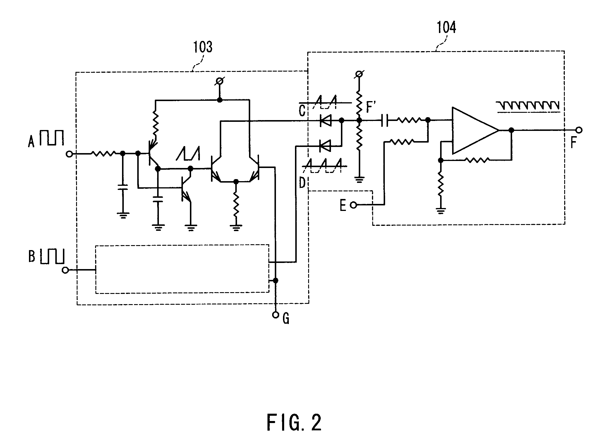
It has been mentioned in the first embodiment that a superimposition amount / timing adjustment signal G (DC level signal) is inputted from the main controlling portion 102 to the waveform converter 103 so as to adjust the amount and timing of superimposing the triangular wave signal. The lamp current iL commutated at the commutator 109 is detected by the current detector R1, and fed back as a lamp current detection signal H into the main controlling portion 102. At the main controlling portion 102, a superimposition amount / timing adjustment signal G is generated according to the amount of feedback of the lamp current detection signal H, and thus the amount and timing for superimposing the tria...
third embodiment
(Third Embodiment)
A third embodiment of the present invention will be described below by referring to FIG. 1 as well. In this embodiment, an amount and timing for superimposing the triangular wave signal onto the current-controlling signal is set variably on the basis of a lamp temperature detected by the lamp temperature detector 111.
It has been mentioned in the first embodiment that a superimposition amount / timing adjustment signal G (DC level signal) is inputted from the main controlling portion 102 to the waveform converter 103 so as to adjust the amount and timing of superimposing the triangular wave signal. The lamp temperature detected by the lamp temperature detector 111 is fed back as a temperature detection signal J to the main controlling portion 102. At the main controlling portion 102, a superimposition amount / timing adjustment signal G is generated according to a feedback mount of the temperature detection signal J so as to adjust the amount and timing of superimposing...
PUM
 Abstract
Description
Claims
Application Information
 - R&D
- Intellectual Property
- Life Sciences
- Materials
- Tech Scout
- Unparalleled Data Quality
- Higher Quality Content
- 60% Fewer Hallucinations
Browse by: Latest US Patents, China's latest patents, Technical Efficacy Thesaurus, Application Domain, Technology Topic, Popular Technical Reports.
© 2025 PatSnap. All rights reserved.Legal|Privacy policy|Modern Slavery Act Transparency Statement|Sitemap|About US| Contact US: help@patsnap.com


