Al technical title is built by PatSnap Al team. It summarizes the technical point description of the patent document.
a technology for shock absorbers and motor vehicles, applied in the direction of bumpers, elastic dampers, vehicle safety arrangments, etc., can solve the problems of material interference or copenetration of the deforming body, and achieve the effect of less fluctuation, constant force, and maximum efficiency of the crash box
Inactive Publication Date: 2014-01-09
IMPERO PASQUALE
View PDF33 Cites 11 Cited by
Summary
Abstract
Description
Claims
Application Information
AI Technical Summary
This helps you quickly interpret patents by identifying the three key elements:
Problems solved by technology
Method used
Benefits of technology
[0015]The crushing of the crash box therefore proceeds with an ordered deformation, that is to say with an accordion-like deformation; in this way, the crash box reacts to the crushing with a less fluctuating and therefore more constant force, which maximizes the efficiency of the crash box.
[0016]In addition, the deformation of the material of the deforming body occurs in a predictable manner in the section of the bead that is located at the edge: this enables a more accurate calculation of the deformation that the crash box would suffer if subjected to an impact, that is to say the way in which it would collapse during the instants subsequent to the impact, which enables the crash box to be more accurately designed with respect to known inventions.
[0017]Therefore beads of greater length can be designed than those present in the prior art inventions cited in the preamble: in fact, a bead may involve two or more walls of each portion of the deforming body or develop along a path that includes the entire width of the relative portion on which the bead itself is incorporated, i.e. along the fixing tabs and the walls of the half-shell. In this way, it is advantageously possible to guide the plastic deformation of the deforming body more precisely and more accurately adjust the amount of energy required to produce a certain degree of deformation of the deforming body as a result of an impact.
Problems solved by technology
An accumulation, interference or copenetration of material of the deforming body would occur, however, if the bead did not vary the orientation thereof, remaining projecting or retracted.
Method used
Image
Click on the blue label to locate the original text in one second.
Reading with bidirectional positioning of images and text.
Examples
Embodiment Construction
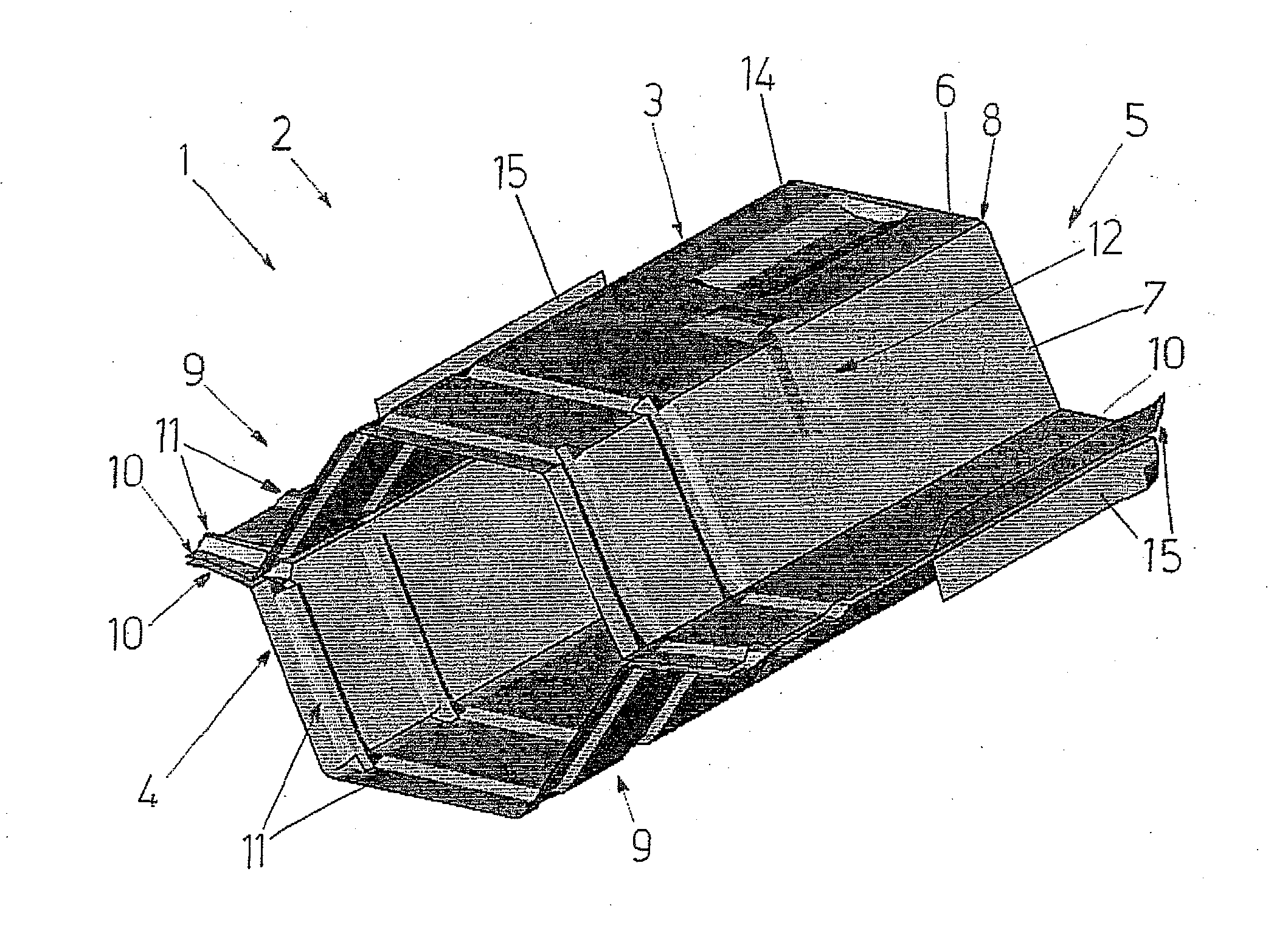
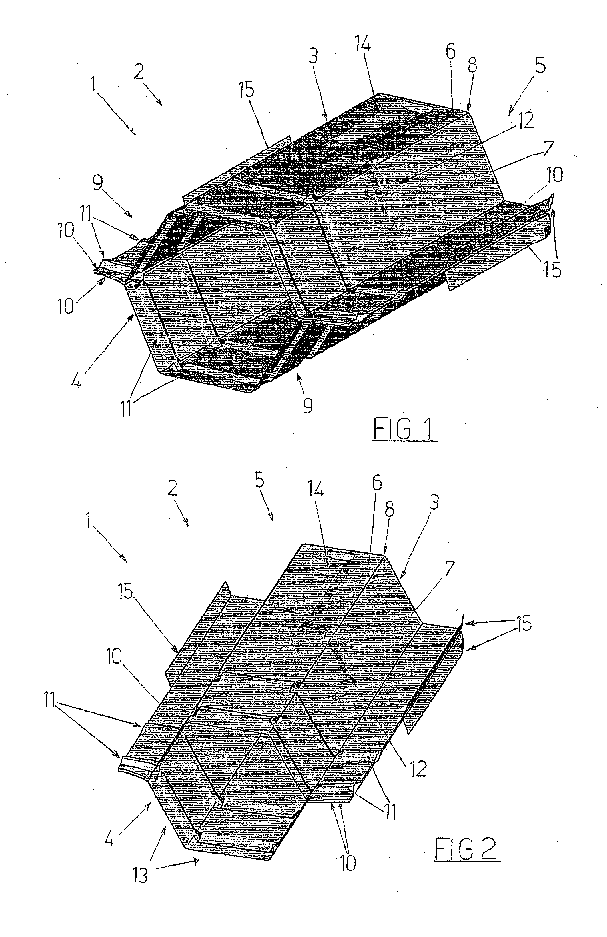
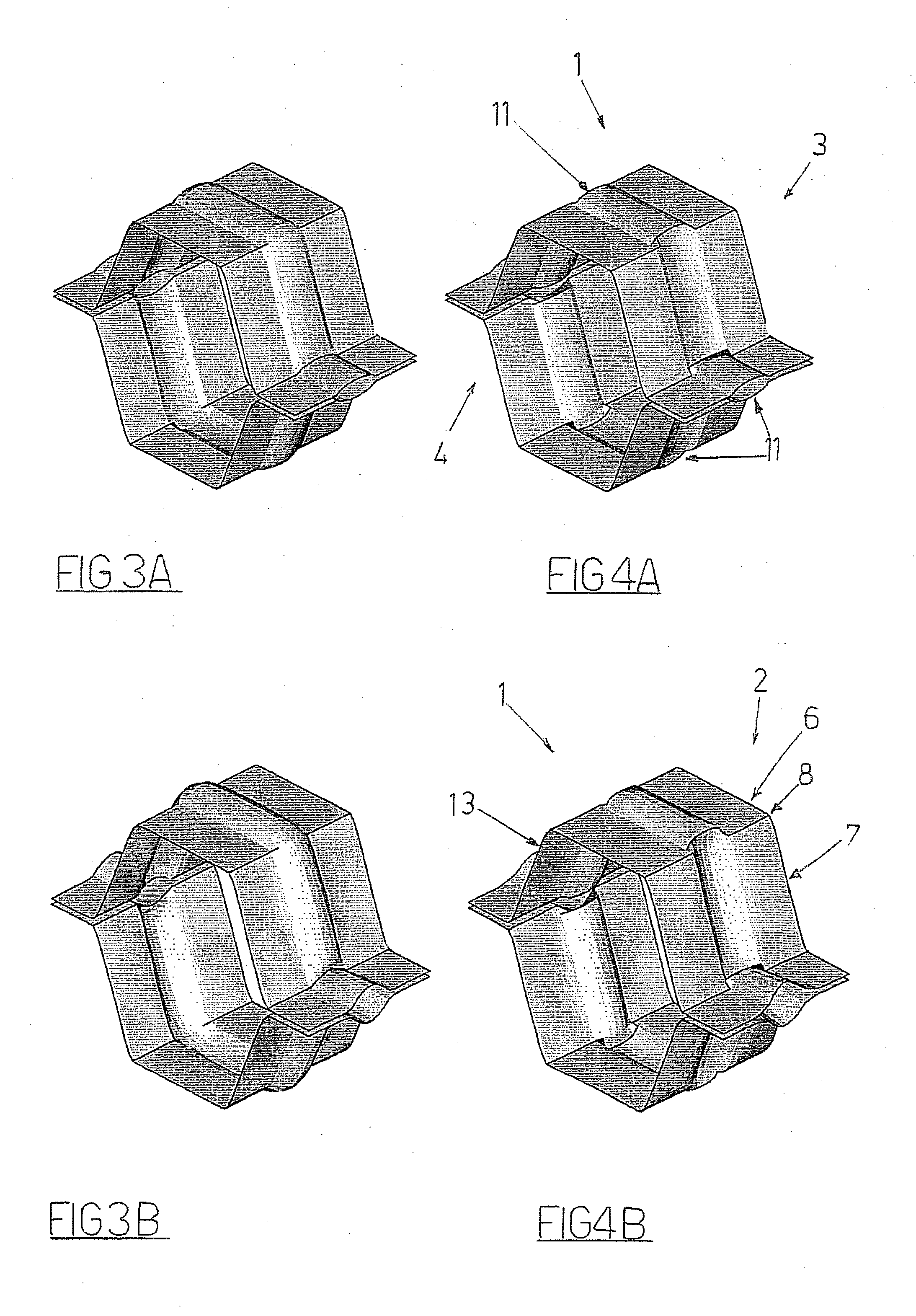
[0023]With reference to FIGS. 1, 2, 4A-4H, (1) denotes in its entirety a crash box, object of the present invention.
[0024]The crash box (1) comprises: a deforming body (2) configured such as to deform if subjected to an impact of a certain entity, the deforming body (2) comprising a first portion (3) and a second portion (4) which are opposite and fixed to one another such as to identify a tubular member (5) which has a first axis and comprises a first wall (6) and a second wall (7) adjacent to one another, which intersect to identify an edge (8).
[0025]Each portion (3, 4) comprises a half-shell (9) and two fixing tabs (10) arranged respectively at opposite ends of the half-shell (9), at least a portion (3, 4) comprising at least a bead (11, 12) which develops along a perpendicular development with respect to the first axis, which bead (11, 12) is conformed such as to guide the plastic deformation of the deforming body (2) and such as to regulate a quantity of energy required for pro...
PUM
Abstract
A shock absorber for motor vehicles, comprising: a deforming body (2) comprising a first portion (3) and a second portion (4) which are fixed to one another such as to identify a tubular member (5) which has a first axis and comprises a first wall (6) and a second wall (7) adjacent to one another, which intersect to identify an edge (8), each portion (3, 4) comprising a half-shell (9) and two fixing tabs (10) arranged respectively at opposite ends of the half-shell (9), at least a portion (3, 4) comprising at least a bead (11, 12) which develops along a perpendicular development with respect to the first axis. The bead (11, 12) develops continuously at least along a part of the first wall (6) and at least along a part of the second wall (7) of the tubular member (5), following at least the edge (8) identified between the first wall (6) and the second wall (7), the bead (11, 12), when it follows the first wall (6), being orientated projecting with respect to the zone of the external surface of the first wall (6) which surrounds the bead (11, 12), the bead (11, 12), when following the second wall (7), being orientated retracted with respect to the zone of the external surface of the second wall (7) which surrounds the bead (11, 12), the bead (11, 12), at the edge (8), varying orientation thereof between projecting and retracted.
Description
FIELD OF THE INVENTION[0001]The present invention relates to the technical sector of shock absorbers for motor vehicles, known as “crash boxes”.DESCRIPTION OF THE PRIOR ART[0002]As known, crash boxes are usually interposed between the front strut of a motor vehicle and the relative front cross beam, and in some cases, the crash boxes are also fixed to the rear cross beams.[0003]Crash boxes comprise a deforming body configured such as to deform when subjected to a compressive stress of a certain entity, for example, an impact; the function of the crash box is such that, for so-called “low speed” impacts, the kinetic energy at the moment of impact is converted into deformation energy of the crash box in order to safeguard the integrity of the vehicle structure.[0004]The state of the art comprises a shock absorber for motor vehicles in which the deforming body is provided with two opposite portions that are also fixed to one another, identifying a tubular member having an elongate deve...
Claims
Application Information
Patent Timeline
Application Date:The date an application was filed.
Publication Date:The date a patent or application was officially published.
First Publication Date:The earliest publication date of a patent with the same application number.
Issue Date:Publication date of the patent grant document.
PCT Entry Date:The Entry date of PCT National Phase.
Estimated Expiry Date:The statutory expiry date of a patent right according to the Patent Law, and it is the longest term of protection that the patent right can achieve without the termination of the patent right due to other reasons(Term extension factor has been taken into account ).
Invalid Date:Actual expiry date is based on effective date or publication date of legal transaction data of invalid patent.
Patent Type & Authority Applications(United States)