
Solid Electrolytic Capacitor and Method for Producing the Same

a solid electrolytic capacitor and capacitor chip technology, applied in the manufacture of electrolytic capacitors, capacitors, capacitors, etc., can solve the problems of increasing leakage current, large equivalent series resistance (esr), and increasing the capacitance of the solid electrolytic capacitor chip, so as to reduce the dielectric loss (tan ), high capacitance, and the effect of reducing the dielectric loss

Inactive Publication Date: 2008-02-28
MURATA MFG CO LTD
View PDF6 Cites 11 Cited by
  • Summary
  • Abstract
  • Description
  • Claims
  • Application Information

AI Technical Summary

Benefits of technology

The present invention relates to a solid electrolytic capacitor and a production method thereof. The method involves polymerizing a monomer on a valve-acting metal surface with an oxidizing agent to form a dielectric film layer, followed by dipping the metal in a monomer-containing solution and an oxidizing agent-containing solution to form a solid electrolyte layer. By controlling the polymerization conditions, the thickness of the electrolyte can be made uniform, resulting in a thin capacitor element with less uneven contact with the dielectric oxide film layer. The invention also allows for a higher number of capacitor elements to be stacked in a chip, increasing the capacitance without increasing the size of the chip. The solid electrolytic capacitor produced using this method has excellent adhesion and high capacitance.

Problems solved by technology

If the polymerization conditions of the electrically conducting polymer in the cathode portion of the capacitor element are not precisely controlled, the thickness of the electrically conducting polymer becomes uneven and the electrically conducting polymer comes to have a thin portion, in which direct contact of the paste or the like with the dielectric oxide film layer readily occurs, giving rise to increase in the leakage current.
Furthermore, since the number of capacitor elements which can be stacked in a solid electrolytic capacitor chip having a predetermined size is limited by the thickness of the element, the capacitance of the solid electrolytic capacitor chip cannot be increased.
In addition, if the coverage thickness of the electrically conducting polymer is not uniform, the contact area between a capacitor element and a capacitor element stacked decreases and this causes a problem that the equivalent series resistance (ESR) becomes large.

Method used


Image

  • Solid Electrolytic Capacitor and Method for Producing the Same
  • Solid Electrolytic Capacitor and Method for Producing the Same
  • Solid Electrolytic Capacitor and Method for Producing the Same

Examples


examples

[0100] The present invention is described in greater detail below by referring to representative examples, but these are mere examples for describing the present invention, and the present invention is not limited thereto. Example 1:

[0101] A chemically formed aluminum foil (thickness: 100 μm) was cut into a size of 3 mm (short axis direction)×10 mm (long axis direction), and a polyimide solution was circumferentially coated on both surfaces in a width of 1 mm to divide the surface into a 4-mm portion and a 5-mm portion in the long axis direction and then dried to provide a masking. A voltage of 4 V was applied to the 3 mm×4 mm portion of this chemically formed foil in a 10 mass % aqueous ammonium adipate solution to chemically form the cut end part and thereby produce a dielectric oxide film. Thereafter, this 3 mm×4 mm portion of the aluminum foil was dipped in a 2.0 mol / L isopropyl alcohol (IPA) solution having dissolved therein 3,4-ethylenedioxythiophene for 5 seconds and after d...

example 2

[0106] A chemically formed aluminum foil. (thickness: 100 μm) was cut into a size of 3 mm (short axis direction)×10 mm (long axis direction), and a polyimide solution was circumferentially coated on both surfaces in a width of 1 mm to divide the surface into a 4-mm portion and a 5-mm portion in the long axis direction and then dried to provide a masking. A voltage of 4 V was applied to the 3 mm×4 mm portion of this chemically formed foil in a 10 mass % aqueous ammonium adipate solution to chemically form the cut end part and thereby produce a dielectric oxide film. Thereafter, this 3 mm×4 mm portion of the aluminum foil was dipped in a 2.0 mol / L isopropyl alcohol (IPA) solution having dissolved therein 3,4-ethylenedioxythiophene for 5 seconds and after drying at room temperature for 5 minutes (Step 1), dipped in a 2.0 mol / L aqueous ammonium persulfate solution adjusted to have a sodium 2-anthraquinonesulfonate concentration of 0.07 mass % for 5 seconds. Subsequently, this aluminum f...

example 3

[0111] A solid electrolyte layer was formed in the same manner as in Example 1 except that in the dipping step in Step 3 of Example 1, a suspension prepared to have a sodium 2-anthraquinonesulfonate (D50=11 μm) concentration of 2 mass % was used in place of distilled water and the number of repetitions of Steps 1 to 3 was changed to 9 times. The residual ratio of the solid electrolyte determined by the same manner as in Example 1 was 79%. The thickness of the aluminum foil was measured in the same manner as in Example 1, as a result, the average film thickness of 120 elements was 146 μm and the standard deviation was 16 μ.

[0112] Thereafter, 30 units of capacitors were completed in the same manner as in Example 1. The properties of the obtained capacitor devices were evaluated in the same manner as in Example 1 and the results thereof are shown in Table 1.


PUM

PropertyMeasurementUnit
timeaaaaaaaaaa
particle diameteraaaaaaaaaa
thicknessaaaaaaaaaa

Abstract

The present invention relates to a method for producing a solid electrolytic capacitor in which a solid electrolyte layer is provided by a process comprising a step of dipping a valve-acting metal having thereon a dielectric film layer in a monomer-containing solution, followed by drying (Step 1), a step of dipping the valve-acting metal in an oxidizing agent-containing solution, followed by drying (Step 2), and a step of dipping the. valve-acting metal in an oxidizing agent-free solution, followed by drying (Step 3); and to a solid electrolytic capacitor produced thereof. According to the present invention, a thin capacitor element with reduced failure of short circuit and less fluctuation in the element shape can be stably produced, the number of capacitor elements stacked in a solid electrolytic capacitor chip can be increased to realize high capacitance, and a solid electrolytic capacitor element suitable for a solid electrolytic multilayer capacitor with less fluctuation in the equivalent series resistance can be provided.

Description

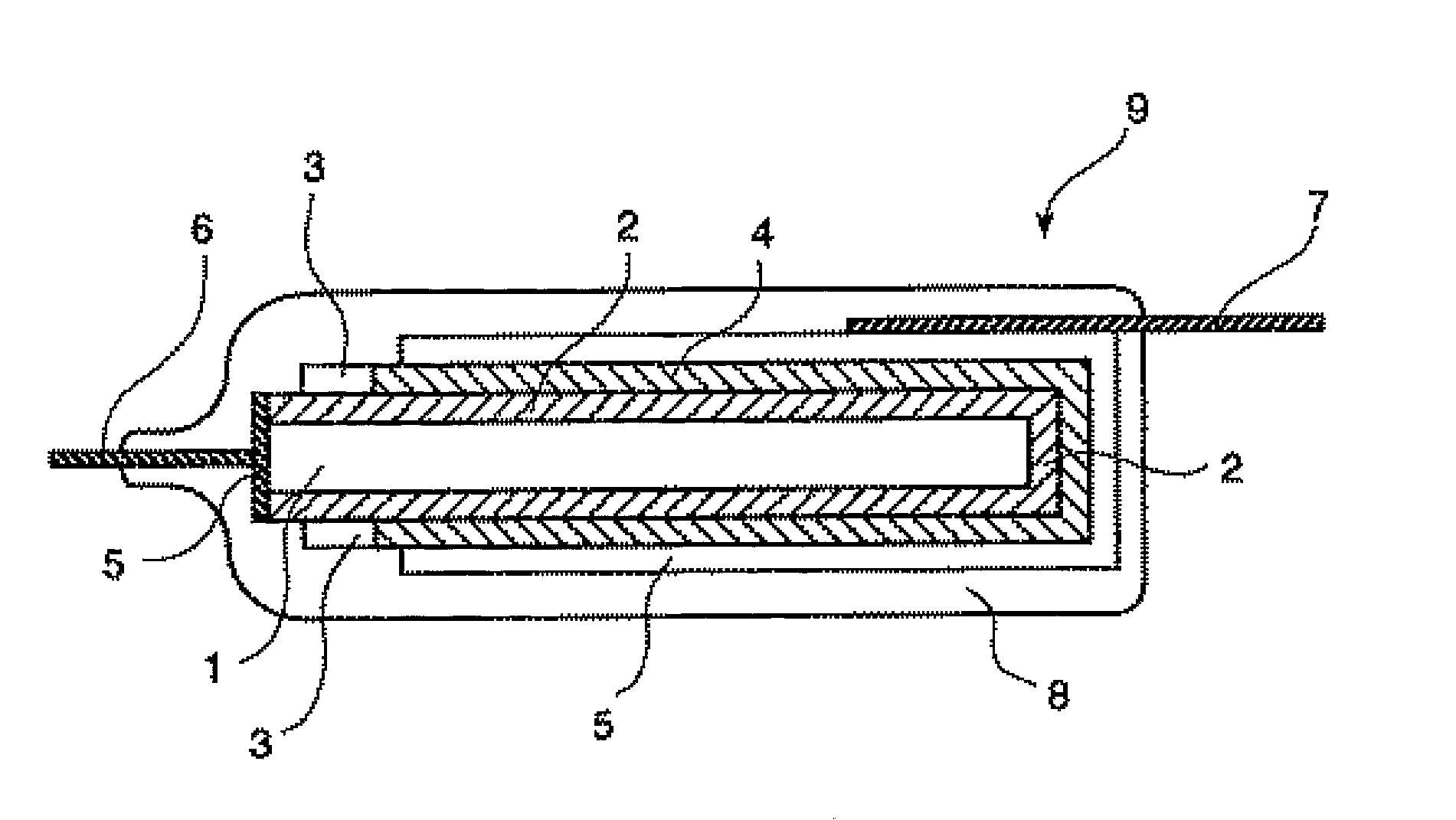
CROSS REFERENCE TO THE RELATED APPLICATIONS [0001] This is an application filed pursuant to 35 U.S.C. Section 111(a) with claiming the benefit of U.S. Provisional Application Ser. No. 60 / 631,988 filed Dec. 1, 2004 under the provision of 35 U.S.C. Section 111(b), pursuant to 35 U.S.C. Section 119(e)(1).TECHNICAL FIELD [0002] The present invention relates to a solid electrolytic capacitor using an electrically conducting polymer as the solid electrolyte layer, and a production method thereof. BACKGROUND ART [0003] The basic element of a solid electrolytic capacitor is generally produced, as shown in FIG. 1, by forming a dielectric oxide film layer (2) on an anode substrate (1) comprising a metal foil subjected to an etching treatment to have a large specific surface area, forming a solid semiconductor layer (hereinafter referred to as a “solid electrolyte”) (4) as a counter electrode on the outer side of the dielectric oxide layer, and preferably further forming thereon an electricall...

Claims


Application Information

Patent Timeline
Patent Type & Authority Applications(United States)
IPC IPC(8): H01G9/15
CPCH01G9/0036H01G9/042H01G9/15Y10T29/417H01G11/48H01G11/56Y02E60/13
Inventor SAIDA, YOSHIHIROKONUMA, HIROSHI
Owner MURATA MFG CO LTD
Learn More