
Determination of data rate, based on power spectral density estimates

a data rate and power spectral density technology, applied in pulse techniques, transmission monitoring, baseband system details, etc., can solve the problems of computational complexity, decrement of the performance of data symbol power estimation, and very dominant noise in the detection process, so as to reduce the snr (signal-to-noise ratio) fluctuation. the effect of sensitiv

Inactive Publication Date: 2007-01-30
NOKIA CORP
View PDF17 Cites 13 Cited by
  • Summary
  • Abstract
  • Description
  • Claims
  • Application Information

AI Technical Summary

Benefits of technology

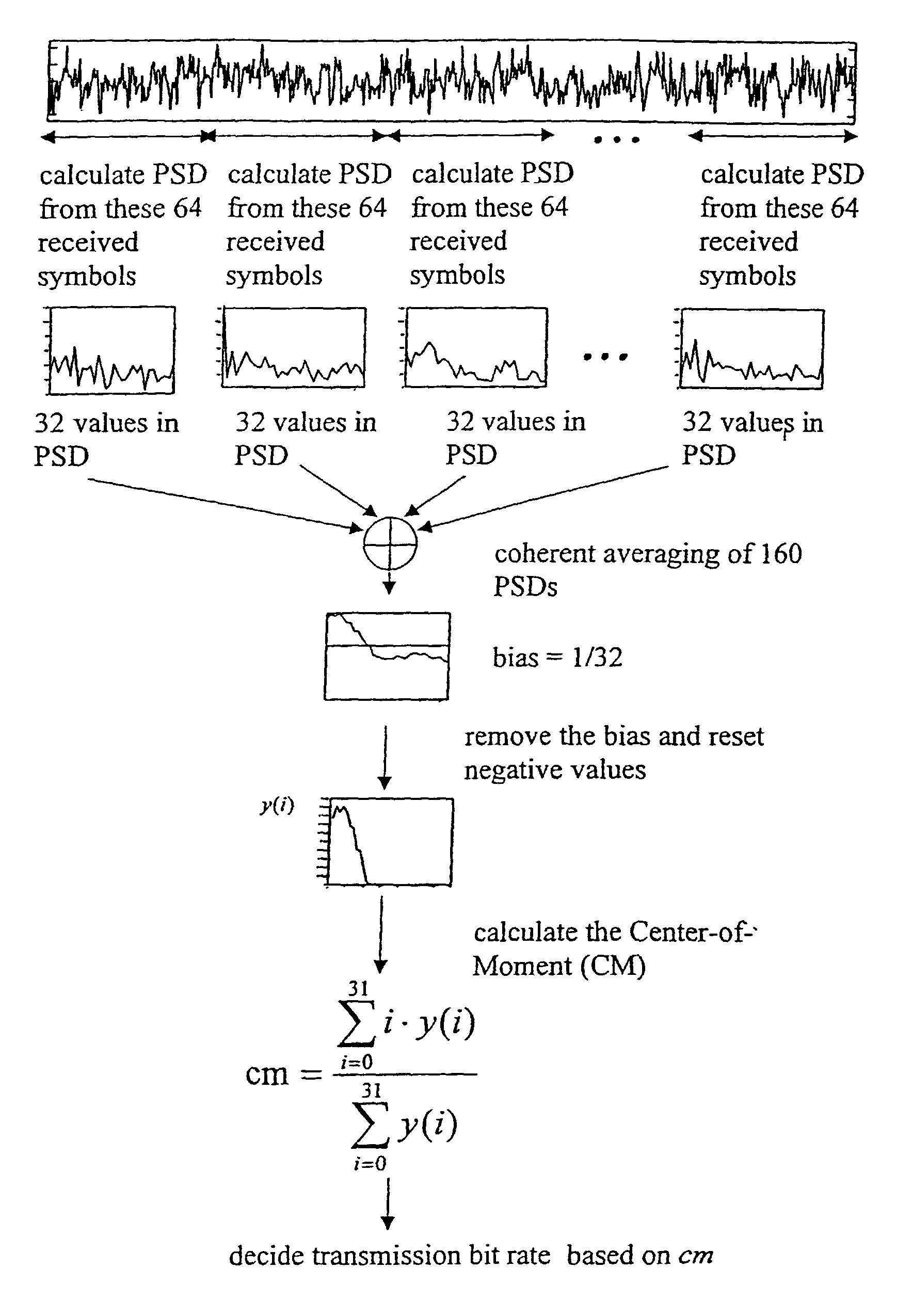
[0020]The embodiments of the present invention provide several advantages. The embodiments of the invention can be used in a situation where no rate information is transmitted. In addition, the embodiments of the invention can be used in a situation where the rate information is transmitted but cannot, for reason or another, be used or detected from the signal during the receiving process. In addition, one possible use is to provide an additional data rate information which can be used e.g. for correction or error check of a rate information detected from the transmitted signal. The estimate of data transmission rate can also be used in other parts of the received signal processing sequence, e.g. in an IC receiver. The possibility for an early detection of the unknown data rate enables use of any such receiver structure which makes use of the data rate information at an early stage. The estimate can also be used to assist in rate selection for Viterbi decoding of the incoming data symbols, or to assist in decision of an alternative transmission rate for decoding if an error check fails. In addition, embodiments of the invention may assist in provision of a system that is less sensitive to SNR (Signal-to-Noise Ratio) fluctuation.

Problems solved by technology

However, the disadvantage of the method is that if a very low spreading factor is used in detecting the data symbols (4 in the above example) in the first place noise becomes very dominant in the detection process.
This degrades substantially the performance of the data symbol power estimation.
A disadvantage of this method is that it is computationally complex: if there are N possible data rates, this requires N consequent CRC decoding processes before a decision of the transmitter data rate can be made.
Moreover, the method does not give any data rate if the algorithm does not give an exactly matching CRC check.
This method, however, is also computationally complex and uses assumptions which may lead to even more complicated arithmetical operations and / or inaccurate results of the estimation procedure.
An additional disadvantage of the two latter prior art methods is that they delay the final decision of the data rate of the received signal to a stage where some decoding of the data is needed for the first time.
This will make the operation difficult for receiver structures that require an estimate of the data transmission rates of the received signals at an earlier stage than decoding.

Method used


Image

  • Determination of data rate, based on power spectral density estimates
  • Determination of data rate, based on power spectral density estimates
  • Determination of data rate, based on power spectral density estimates

Examples


Embodiment Construction

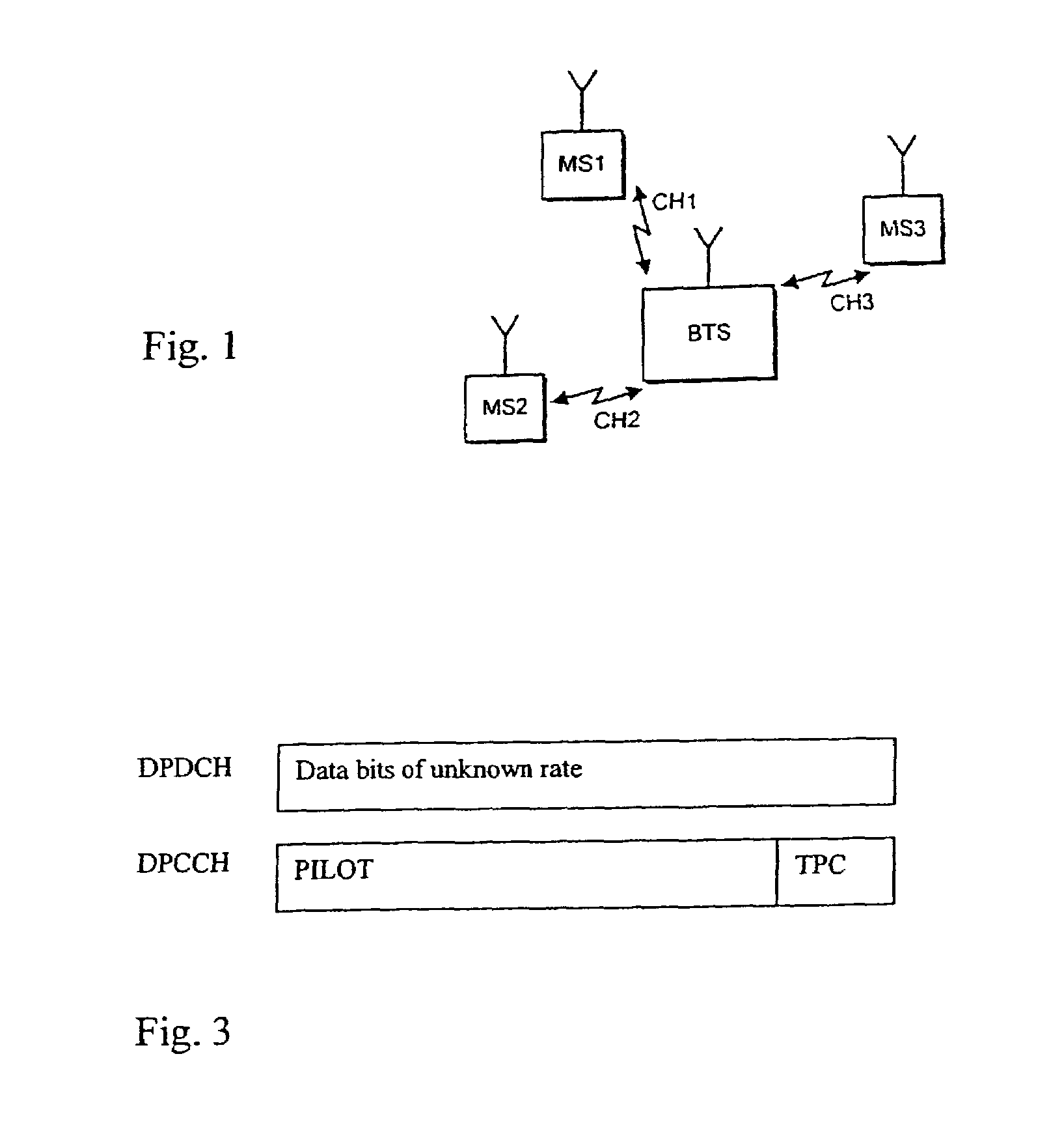
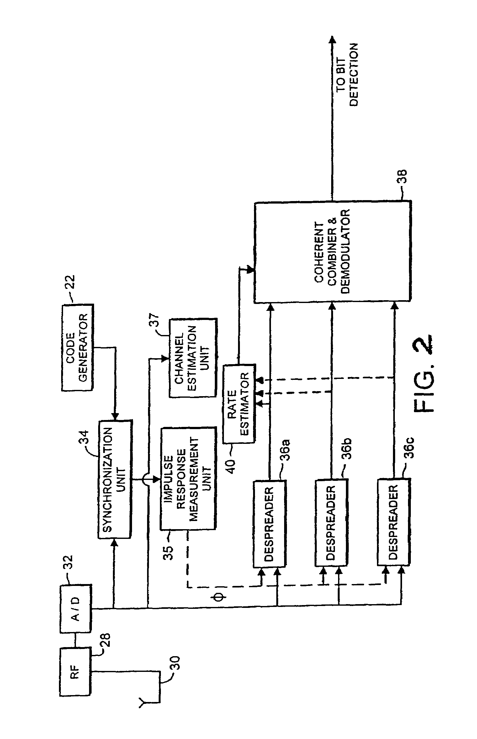
[0027]FIG. 1 is a block diagram illustrating a context in which the present invention may be used. That is, a CDMA mobile communication system allows a plurality of mobile stations MS1, MS2, MS3 to communicate with a base (transceiver) station BTS in a common cell via respective channels CH1, CH2, CH3. These channels are distinguished from one another by the use of scrambling codes in a manner which is know per se. FIG. 2 is a block diagram of a receive circuitry at a base station in a WCDMA system (Wideband CDMA). The receive circuitry of FIG. 2 is for use in uplink direction, i.e. for receiving signals from the mobile stations (MS). It is noted that even though the actual receive circuitry implementation in the downlink direction, i.e. at the mobile station, can be somewhat different, the invention is applicable to downlink transmissions as well.

[0028]Before describing the exemplifying receiving circuitry of FIG. 2 in more detail, a transmit circuitry (not shown) within a transmit...


PUM


Abstract

The present invention relates to a method and a circuitry for estimating data transmission rate in a communication system. The communication system utilizes variable data transmission rates. A transmission signal between two stations of the system includes a plurality of data symbols over a sequence of data frames. A data frame of a received transmission signal is classified in accordance with a predefined classification of the data transmission rates, whereafter the data transmission rate of the received data frame is estimated on basis of said classification.

Description

CROSS-REFERENCE TO RELATED APPLICATION[0001]Priority is claimed from International Application PCT / EP99 / 06719, filed Sep. 9, 1999.FIELD OF THE INVENTION[0002]The present invention relates to a method and circuitry for estimating data rates of signals transmitted between stations in a communication system, and more particularly, but not explicitly, between stations in a cellular code division multiple access (CDMA) communication system.BACKGROUND OF THE INVENTION[0003]In a communication system signals can be transmitted with variable data transmission rates wherein data is transmitted as a plurality of data symbols in subsequent data frames. As is known, in a cellular CDMA (Code Division Multiple Access) system data is encoded for transmission by modulating data symbols to be transmitted by a spreading code and a unique scrambling code for each channel. Within each cell of the cellular communication system, scrambling codes are preferably as far as possible orthogonal to allow for a ...

Claims


Application Information

Patent Timeline
Patent Type & Authority Patents(United States)
IPC IPC(8): H04B3/46H04L25/02H04J13/00H04W88/00
CPCH04L25/0262H04B2201/70701H04L25/0216
Inventor HORNEMAN, KARIKEISALA, JYRKI
Owner NOKIA CORP
Learn More