
Shin rest

a technology for shins and thighs, applied in the field of shin rests, can solve the problems of prolonged period and intense discomfort in the lower extremities of people, and achieve the effect of reducing the risk of injury

Inactive Publication Date: 2004-01-08
SVEILICH IAN J
View PDF0 Cites 7 Cited by
  • Summary
  • Abstract
  • Description
  • Claims
  • Application Information

AI Technical Summary

Benefits of technology

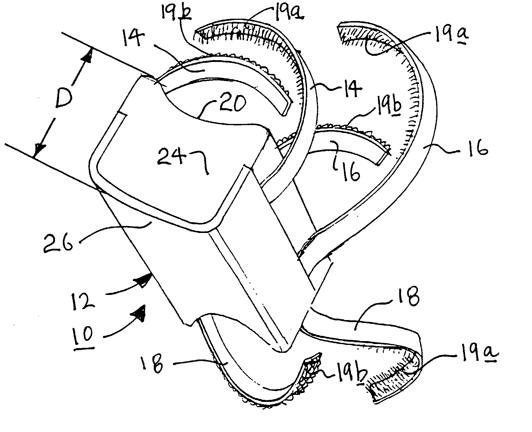
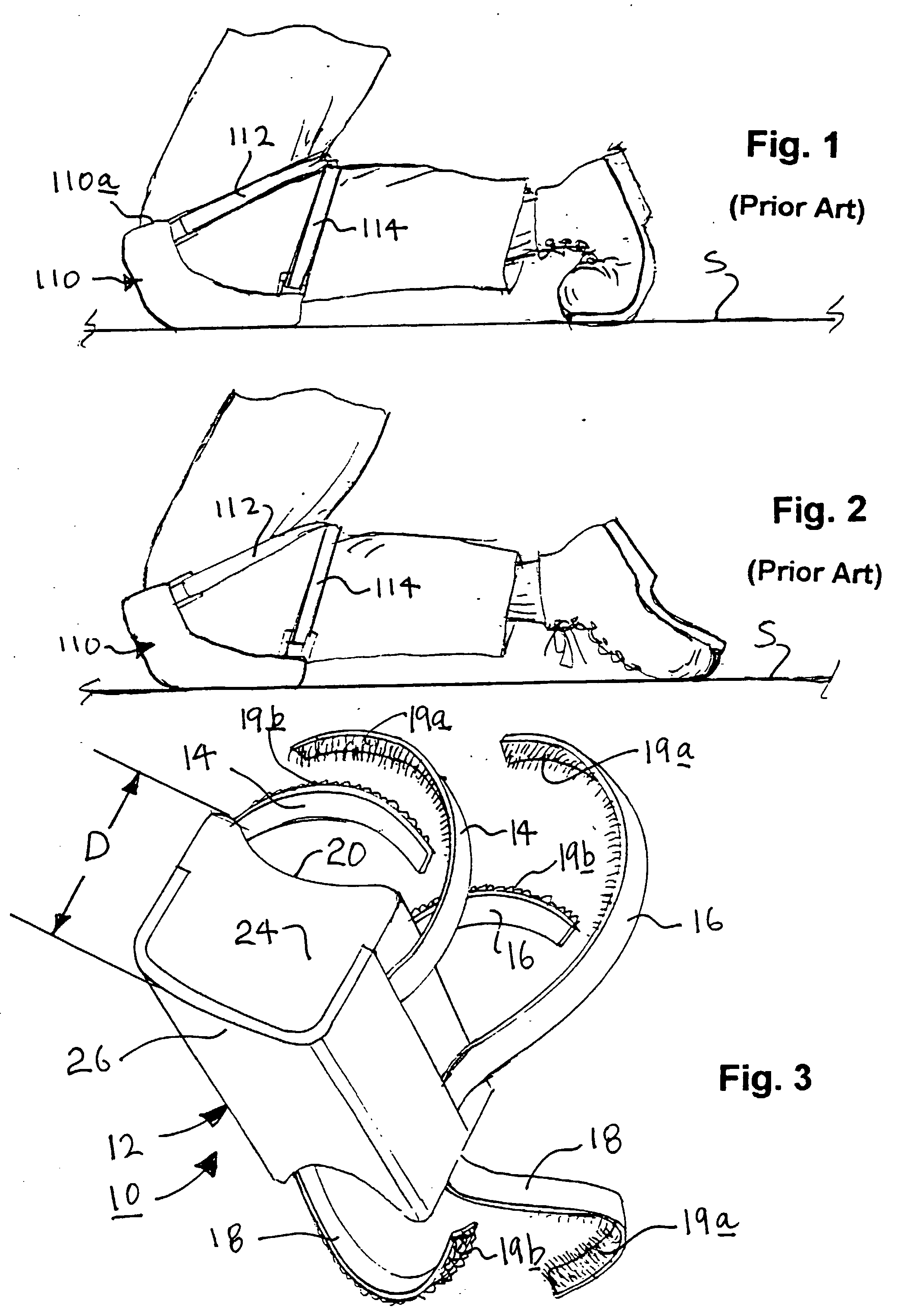
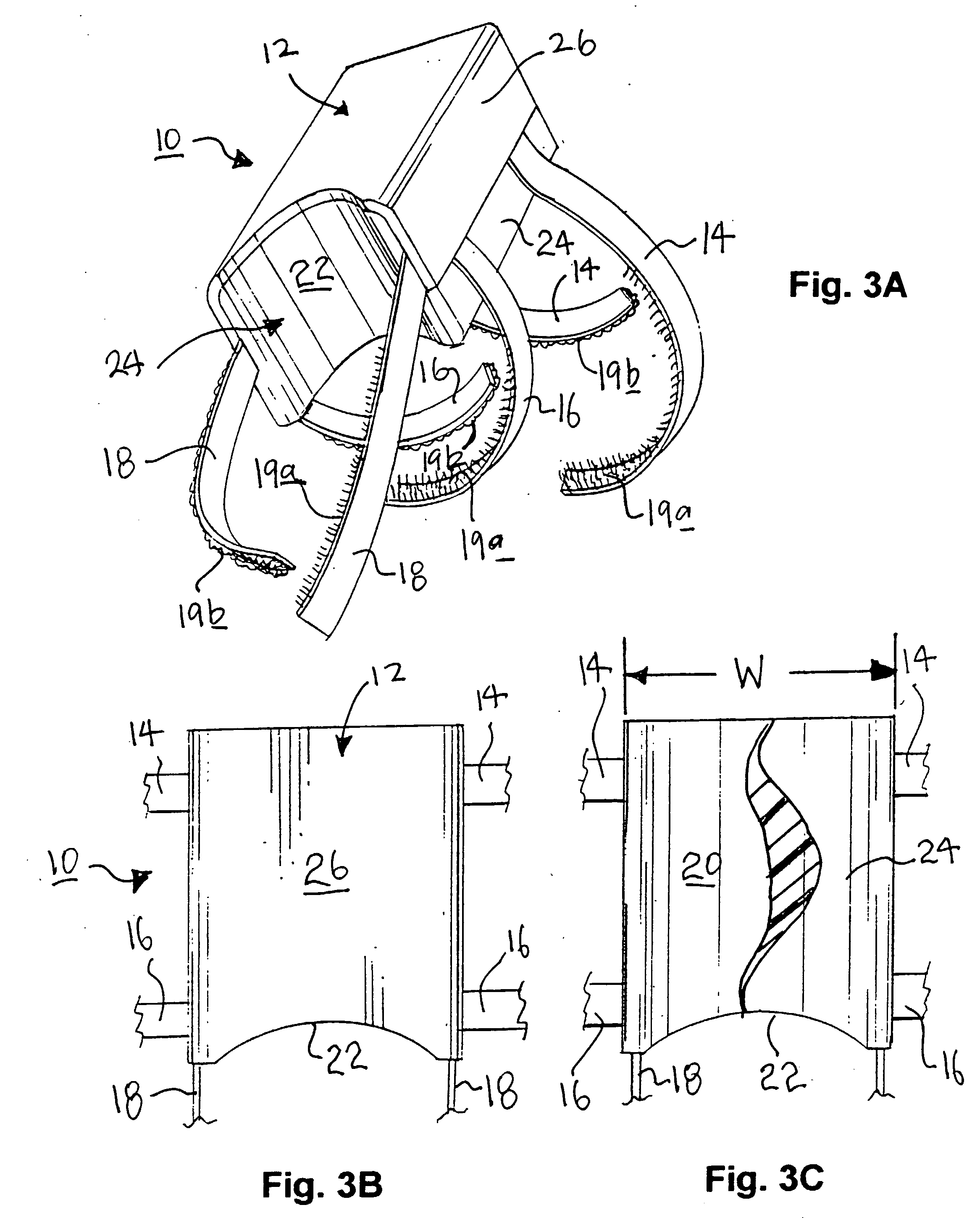
[0006] Specifically, in accordance with the present invention there is provided a shin rest having a body portion which is dimensioned and configured to have a length which extends from about the top of a wearer's foot at least to a point below the wearer's knee, a width which is at least sufficient to provide stable support for the wearer's leg when the wearer is in a kneeling position, and a depth, at least in the vicinity of the top of the wearer's foot, which is sufficient to provide support to the wearer's leg whereby to reduce the force imposed on the wearer's foot when the wearer is in a kneeling position, as compared to the force which, in the absence of the shin rest, would be imposed on the same wearer's foot in the same kneeling position. The body portion has connected to it one or more fasteners, e.g., straps. The fasteners are dimensioned and configured to secure the shin rest to the wearer's leg.
[0007] Another aspect of the present invention provides a shin rest comprising the following components. A body portion comprised of (a) an outer shell having an outside surface and an inside surface, and (b) a cushion liner disposed on the inside surface of the shell is dimensioned and configured as follows. The body portion extends from about the top of a wearer's foot to at least a point on the wearer's shin below the knee, is of a width at least sufficient to provide stable support for the wearer's leg when the wearer is in a kneeling position, and is of a depth at least sufficient to reduce the force imposed on the wearer's foot when the wearer is in a kneeling position, as compared to the force which, in the absence of the shin rest, would be imposed on the same wearer's foot in the same kneeling position. One or more fasteners are connected to the body portion and are dimensioned and configured to secure the shin rest to the wearer's leg.

Problems solved by technology

Most people find that kneeling for a protracted period can generate intense discomfort in their lower extremities.

Method used


Image

  • Shin rest
  • Shin rest
  • Shin rest

Examples


second embodiment

[0028] FIG. 5 shows the present invention comprising a shin rest 210, parts of which are identical to those of the embodiment of FIG. 3B, and are numbered identically to those of FIG. 3B. These identical parts therefore need not be further described. Shin rest 210 differs from shin rest 10 of FIGS. 3-3C in that there is disposed on the outside surface (unnumbered) of outer shell 26 a plurality of bumper strips 28 which comprise raised strips of a soft, resilient material such as rubber, or a resilient, soft plastic material. Bumper strips 28 serve to prevent the rigid shell 26 from marring the surface on which the wearer is kneeling, e.g., a finished wood floor.

third embodiment

[0029] FIG. 6 shows the present invention wherein the shin rest 310 extends from about the top of the wearer's foot to above the wearer's knee and is comprised of a shin pad 30 and a knee pad 32. An articulatable joint 34 connects shin pad 30 to knee pad 32, thereby enabling shin pad 32 to flex to accommodate the wearer's movement, i.e., rising from and returning to a kneeling position. The lower portion, i.e., the portion closest to the wearer's foot, of shin pad 30 is constructed to be substantially the same as that illustrated with respect to the embodiment of FIGS. 3-3C. Bumper strips such as bumper strips 28 of the embodiment of FIG. 5 may extend along the entire length of shin pad 30, and for at least that portion of knee pad 32 which comes into contact with the surface S on which the wearer is kneeling. (Bumper strips 28 are not shown in FIG. 6.) As with the other embodiments, fasteners in the form of straps 36, 38, 40 and 42 are provided to enable the wearer to strap shin re...


PUM


Abstract

A shin rest (10) worn by someone who is kneeling enables the wearer's shin to bear at least some of his or her weight to thereby reduce the stress imposed on the wearer's feet. The shin rest (10) also allows the user to sit back on his or her heels without bringing undue weight to bear on the ankle or the ball of the foot. The shin rest (10) has a body portion (12) that contacts the surface S on which the wearer is kneeling, and thereby supports at least some of the weight and resultant stress otherwise imposed upon the wearer's feet while the wearer is in a kneeling position. The body portion (12) is held to the user's leg by a plurality of straps (14, 16, 18). In a preferred embodiment, the body portion (12) of the shin rest (10) comprises a relatively hard outer shell (26) and a relatively soft cushion liner (24).

Description

[0001] 1. Field of the Invention[0002] This invention pertains to devices, referred to herein as "shin rests", that are attachable to a wearer's leg to prevent strain and / or discomfort, especially to the feet and ankles, while the wearer is in a kneeling position.[0003] 2. Related Art[0004] Various kinds of activities require a person to assume a kneeling position for extended periods of time, for example, gardening, landscaping, tiling, installation of flooring or carpeting, and roofing. Most people find that kneeling for a protracted period can generate intense discomfort in their lower extremities. A partial solution for the alleviation of such discomfort is the known use of knee pads, which provide a cushion that is worn over the knees to cushion the knees from bearing directly against a hard surface or object.[0005] Generally, the present invention provides a shin rest that is worn to support at least the wearer's shins and ankles while the wearer is in a kneeling position. The...

Claims


Application Information

Patent Timeline
Patent Type & Authority Applications(United States)
IPC IPC(8): A41D13/06
CPCA41D13/065
Inventor SVEILICH, IAN J.
Owner SVEILICH IAN J
Learn More