Quick installing, electric chime and back box

a technology of electric chime and back box, which is applied in the direction of electrical apparatus casing/cabinet/drawer, coupling device connection, transformer/react mounting/support/suspension, etc., can solve the problems of only screwing the chime to the sheetrock, the location of the splice box is not very substantial, and the system is very fragmented

Inactive Publication Date: 2004-01-29
BARNES R LLOYD
View PDF4 Cites 8 Cited by
  • Summary
  • Abstract
  • Description
  • Claims
  • Application Information

AI Technical Summary

Problems solved by technology

These systems were very fragmented due to the location requirements of the NEC.
The big problem for this was the location of these splice boxes.
If backing is not placed in the wall then the chime is only screwed to the Sheetrock, which is not very substantial.
It was the electrician's intent to set the transformer in this box, but the installation was rejected because it did not meet code.
The chime was unscrewed from the wall where it was covering the box, because the inspector was suspicious about its compliance with code.
It is an awkward place to install the transformer and requires a blank 2 gang plate to cover it.
The blank plate does not make a pretty installation.
The hand hole provided by the 2 gang plaster ring does not allow much room for grasping the transformer if a change out is required.
Because access is required for the transformers and given the restrictions of mixing class 1 and class 2 wire together, there is presently no other way to make this installation.
What is available is not designed for the purpose and would be much more expensive.
Large surface mounted enclosures are available but would only add to the bad looks of this installation.

Method used


Image

  • Quick installing, electric chime and back box
  • Quick installing, electric chime and back box
  • Quick installing, electric chime and back box

Examples


Embodiment Construction

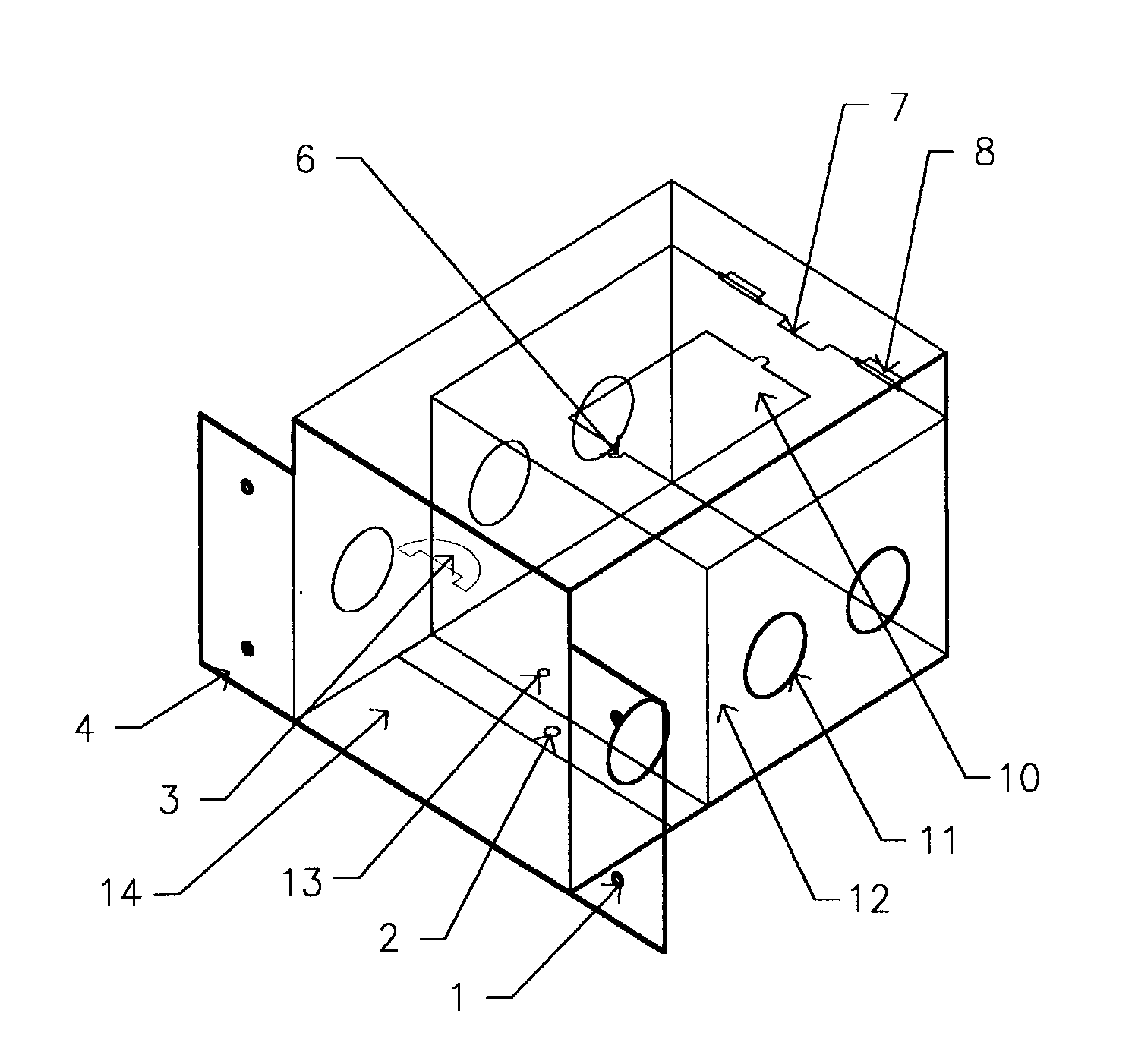
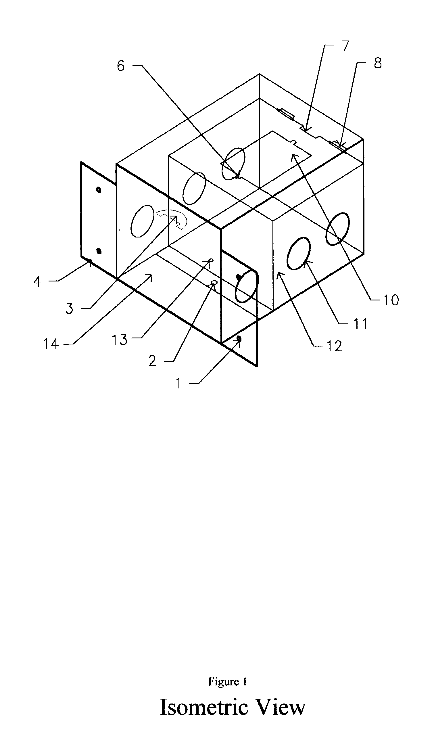
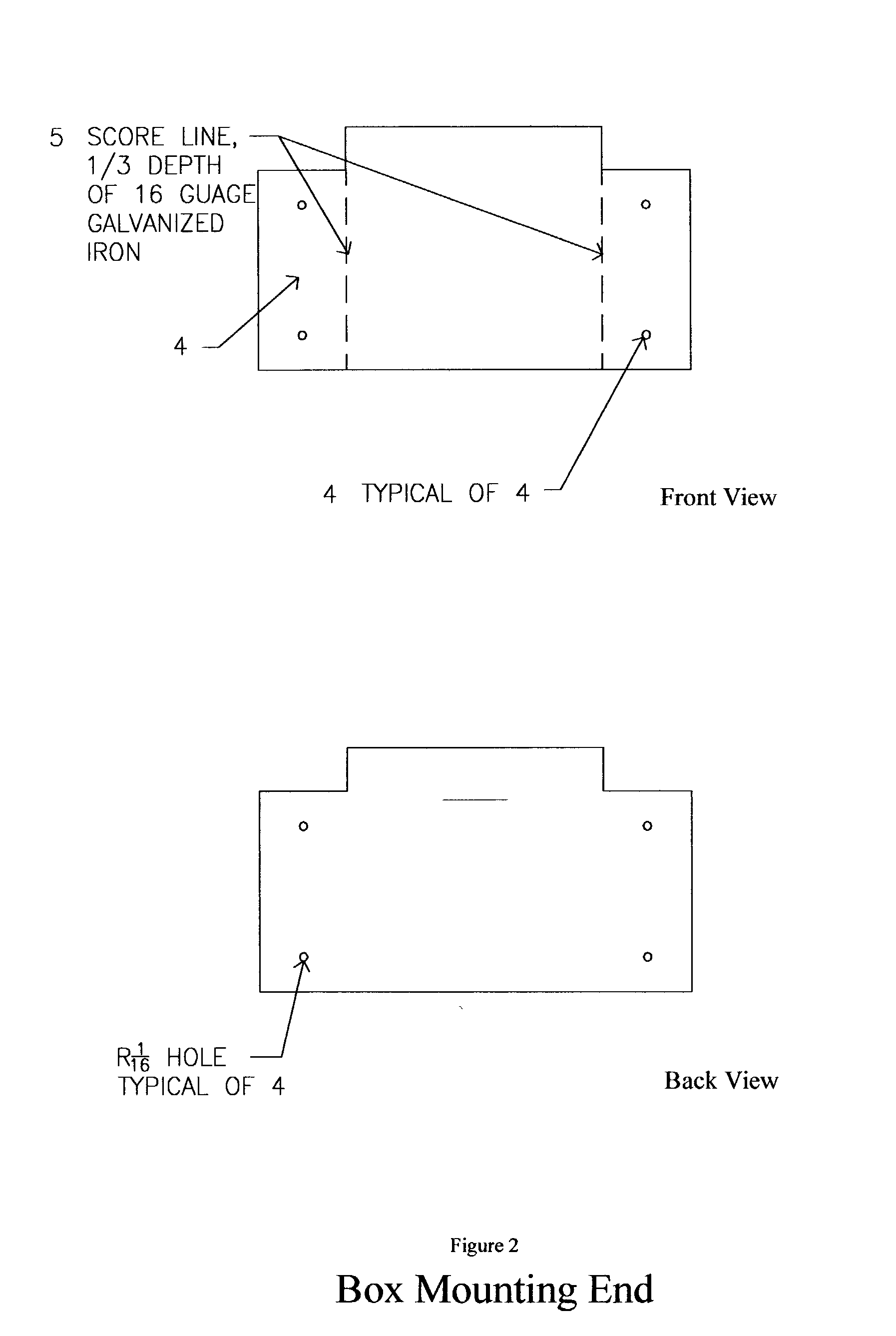
[0059] A preferred embodiment of the box of the present invention is illustrated in FIGS. 1 thru 7. The box is constructed of 16 gage galvanized sheet metal. The front of the box as shown in FIG. 2, is large enough to secure the box in a horizontal or a vertical direction by use of screws or nails through the holes in flange, FIG. 4. If box is to be mounted in masonry units, then the flange FIG. 4 would be broken off top and bottom at FIG. 5, thus creating a nice square box that could be easily mounted flush in the masonry location. In the mounted position, the box is ready to receive its electrical wiring through knockouts displayed in FIG. 5 and FIG. 6. These knockouts are sized for use with 1 / 2" conduit or NM type cable requiring 1 / 2" connectors. In masonry units the flange in FIG. 4 would be broken off at FIG. 5. The 24 v wire for all uses will enter either right or left through knockouts 11 of the low voltage compartment which area is closest to FIG. 2. The 120 v conduit will b...


PUM

PropertyMeasurementUnit
voltageaaaaaaaaaa
voltageaaaaaaaaaa
sizeaaaaaaaaaa

Abstract

An electrical back box of galvanized metal or plastic with a barrier mounted in its interior. This barrier is the support for a low voltage transformer and the means of separating the low and high voltage wiring chambers. Knockouts provide access into these tow chambers for the required electrical wires. Retainer slots located in the interior of the box at the mounting end and at the opposite end provide and insertion point for wire springs. These wire springs are attached to a chime or any type of equipment that may utilize this backbox. When thrust into the retention slots, these springs provide a pulling force that snug the equipment up to the opening of the box. When this back box and transformer are used only for a source of low voltage power then there are two different types of covers that will cover the opening either flush or surface mounted and these make it electrically safe. These covers are mounted by the same wire springs method and are of plastic. When a metal cover is required then it will be supplied with a means of bonding to the equipment ground in the box thus providing electrical fault protection. When different size transformers are needed they can be mounted to the removable barrier but will require the mounting hole in the barrier to be individually sized.

Description

FEDERALLY SPONSORED RESEARCH[0001] Not applicableSEQUENCE LISTING OR PROGRAM[0002] Not applicable[0003] 1. Field of the Invention[0004] This invention brings together an electric door chime, its transformer and an enclosure that combines them all into one assembly.[0005] 2. Description of Prior Art[0006] Chimes (doorbells) have been installed in living units for most of the last century. While these have been effective enough in signaling occupants of these dwellings, the process of installation has changed through the years. The National Fire Protection Association and its electrical code body, NEC, have regulated installations of chime (doorbell) systems with equipment bearing the Underwriters Laboratory seal of approval. These systems were very fragmented due to the location requirements of the NEC. Bell transformers needed to be mounted to an electrical box so that they were on the outside and their 120 volt wires (Primary side) were in the inside where they could be spliced to ...

Claims


Application Information

Patent Timeline
Patent Type & Authority Applications(United States)
IPC IPC(8): H01F27/06H02G3/12
CPCH01F27/06Y10S248/906H02G3/121
Inventor BARNES, R. LLOYD
Owner BARNES R LLOYD
Why Eureka
Try Eureka