
System for inputting speech, radio receiver and communication system

a communication system and speech technology, applied in the field of speech inputting systems, can solve the problems of noise output, noise cannot be cancelled, noise cannot be suppressed enough,

Inactive Publication Date: 2004-03-25
D & M HOLDINGS INC
View PDF2 Cites 28 Cited by
  • Summary
  • Abstract
  • Description
  • Claims
  • Application Information

AI Technical Summary

Problems solved by technology

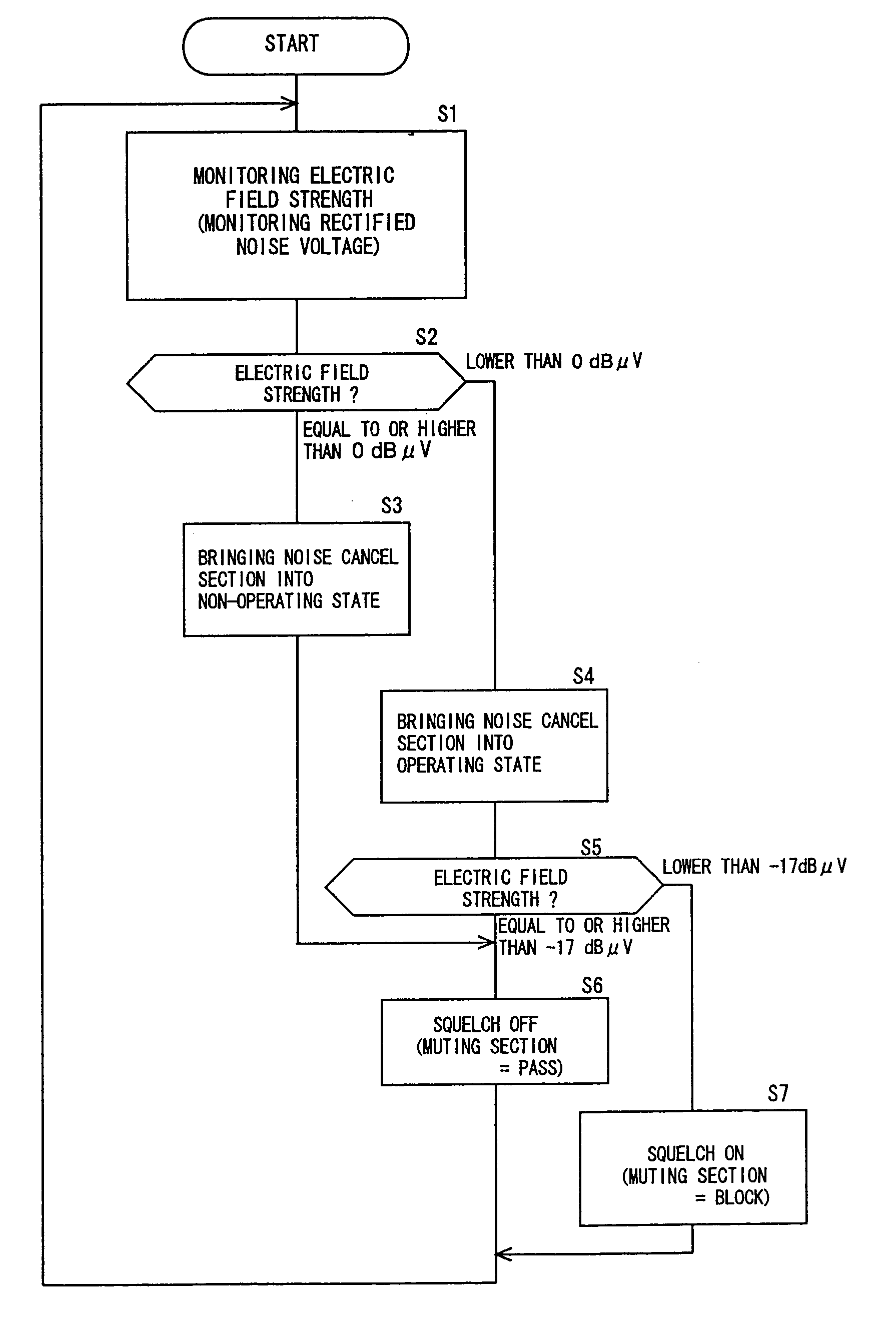
With such radio receiver, however, when the radio waves are received in a weak electric-field region, noise cannot be suppressed enough as a result of which a low-frequency signal containing noise is reproduced.
Also, when the desired radio waves are not received (in a no-signal condition), only noise is outputted as the low-frequency signal.
However, when the noise originates from a direction which is different in angle from the specific direction, when the noise is received from a direction different in angle from the specific direction due to the reflection by an obstacle or when the noise originates from the background in the same direction as the objective sound, the noise cannot be cancelled.
However, when there is no substantial difference in level between the speech signal and the noise or when the noise signal is larger than the speech signal, the noise components cannot be removed.
However, when the tone or volume of the noise abruptly changes, the estimated pseudo noise components will not agree with the received noise components, which will bring about another problem that the speech signal after the removal of the pseudo noise components will make somewhat unnatural sounds containing different noise.

Method used


Image

  • System for inputting speech, radio receiver and communication system
  • System for inputting speech, radio receiver and communication system
  • System for inputting speech, radio receiver and communication system

Examples


Embodiment Construction

[0082] A system for inputting speech and a communication system according to embodiments of the invention will now be described in detail with reference to the accompanying drawings. It is noted, however, that the present invention should not be limited to the specific embodiments as described herein. In the following, description will be made of a specific example of the communication system in which wireless communication is used.

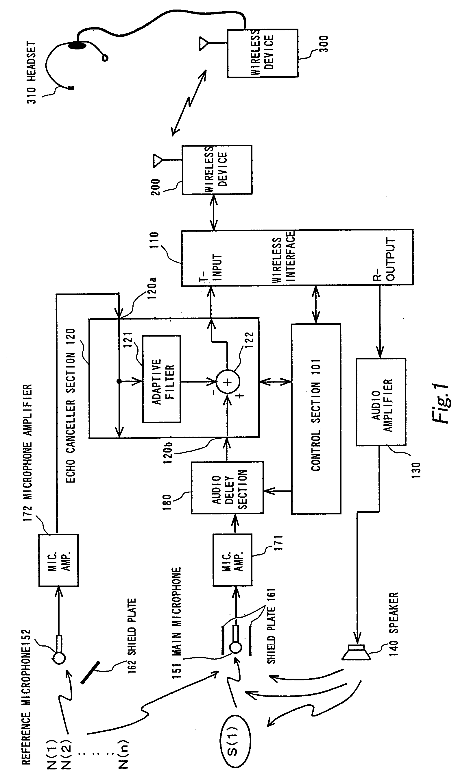
[0083] FIG. 1 is a functional block diagram showing the electrical structure of a first embodiment of the invention.

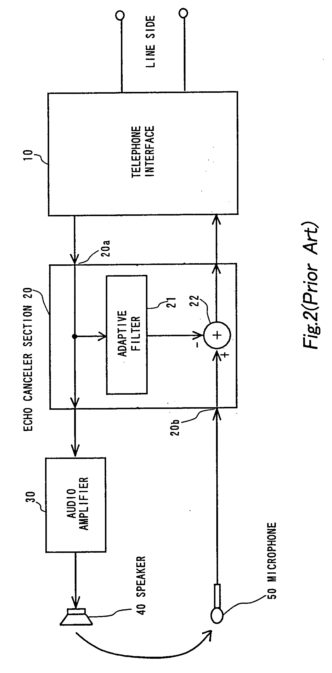
[0084] FIG. 2 is a block diagram for explaining the original manner of use of an echo canceller section which is a principal constituent part of the speech input system according to the first embodiment of the invention.

[0085] First, a system in which the echo canceller is used for its original purpose is described with reference to FIG. 2.

[0086] Shown at 10 is a telephone interface which is connected on its line side (right-hand side in the...


PUM


Abstract

There is disclosed a system for inputting speech that comprises an echo canceller section 120 for subtracting a pseudo echo signal, generated by an adaptive filter 121 based on a speech signal inputted to a first input terminal 120a, from a speech signal for sending as inputted to a second input terminal 120b to thereby remove echo components contained in the speech signal for sending; a main microphone 151 for mainly receiving sound from an objective sound source; a reference microphone 152 disposed a predetermined distance apart from the main microphone 151 for mainly receiving sound from other than the objective sound source; and an audio delay section 180 for giving a predetermine delay to the speech signal for sending from the main microphone 151. The speech signal from the reference microphone 152 is inputted to the first input terminal 120a of the echo canceller section 120, while the speech signal for sending which is from the main microphone 151 and to which the delay has been given in the audio delay section 180 is inputted to the second input terminal 120b of the echo canceller section 120. The delay at the audio delay section 180 is adjusted within a range of delay time of the echo components which the echo canceller section 120 removes. According to this speech input system, the noise is well removed regardless of directions of the sources of the objective sound and the noise, regardless of the difference in level between the objective sound and the noise and / or regardless of whether the noise abruptly changes its tone or volume, so that a clear speech input is achieved even in such a condition that there is noise in the surrounding environment.

Description

BACKGROUD OF THE INVENTION[0001] This invention relates generally to a system for inputting speech and a communication system, and more particularly to such a system for inputting speech and a communication system which are suitable for achieving a clear speech input even under the condition that noise is present in the environment where a communication device for the system is used.[0002] There has been known a technical means called "noise canceller" which is provided, in a speech-input system for use in a communication system, to achieve a clear speech input even under the condition that noise is present in the environment where a communication device for such a system is used.[0003] As, representative techniques for such a noise canceller, the following ones (a), (b) and (c) have widely been known:[0004] (a) First and second microphones are arranged in a mutually spaced relation. A difference between a delayed signal of an output of the second microphone and an output of the fir...

Claims


Application Information

Patent Timeline
Patent Type & Authority Applications(United States)
IPC IPC(8): H03G3/34H04M9/08
CPCH04M9/082H03G3/341
Inventor OHTOMO, MASANOBU
Owner D & M HOLDINGS INC
Learn More