Antenna structure for electronic device with wireless communication unit

a technology of electronic devices and antennas, applied in the field of diversity-type antenna technology, can solve problems such as difficulty in mounting four antennas

Inactive Publication Date: 2004-04-15
KK TOSHIBA
View PDF4 Cites 152 Cited by
  • Summary
  • Abstract
  • Description
  • Claims
  • Application Information

AI Technical Summary

Problems solved by technology

However, in small-sized electronic devices such as notebook-sized personal computers and portable information terminals, it is difficult to mount four antennas because of severe restrictions in mounting components.

Method used


Image

  • Antenna structure for electronic device with wireless communication unit
  • Antenna structure for electronic device with wireless communication unit
  • Antenna structure for electronic device with wireless communication unit

Examples


second embodiment

[0053] (Second Embodiment)

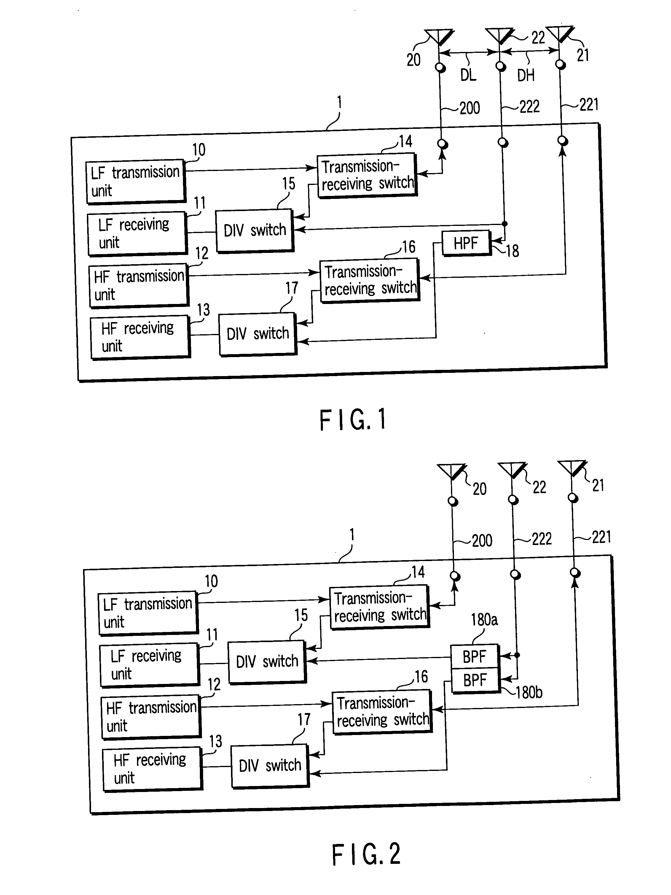
[0054] FIG. 2 is a diagram showing a second embodiment.

[0055] In the electronic device 1 of the present embodiment, the receive-dedicated antenna 22 is connected to band pass filters (BPF) 180a, 180b in the wireless communication unit via the coaxial cable 222.

[0056] The BPF 180a is connected to the DIV switch circuit 15 to extract a frequency signal adaptive to the LF band from a radio frequency signal received by the receive-dedicated antenna 22. On the other hand, the BPF 180b is connected to the DIV switch circuit 17 to extract a frequency signal adaptive to the HF band from a radio frequency signal received by the receive-dedicated antenna 22.

[0057] Such a configuration can also realize the diversity type of antenna structure adaptive to the LF and HF frequency bands, similarly to the primary embodiment. It should be noted that the configuration of other parts is the same as that in the primary embodiment shown in FIG. 1 and will not be described.

third embodiment

[0058] (Third Embodiment)

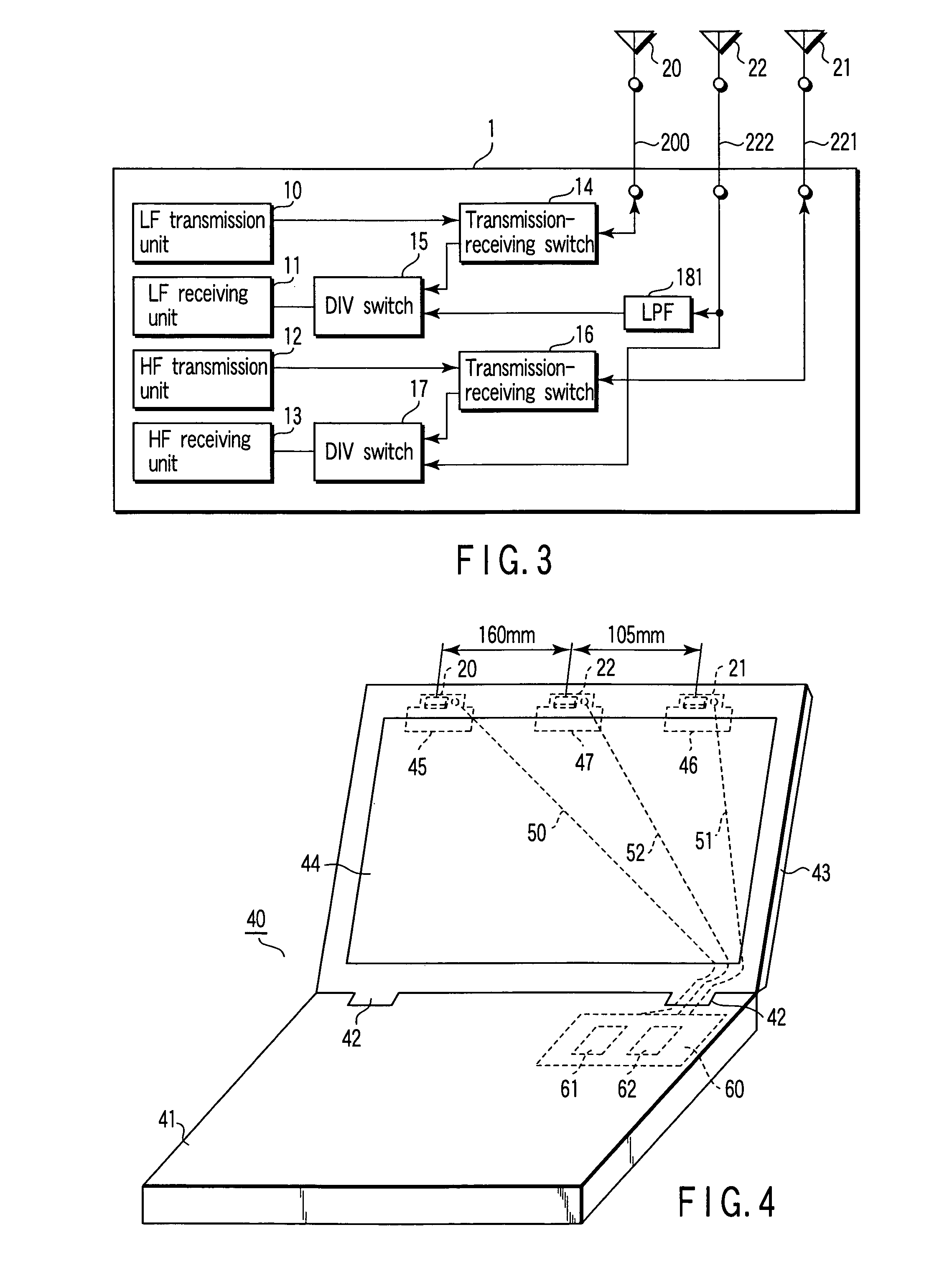
[0059] FIG. 3 is a diagram showing a third embodiment.

[0060] In the electronic device 1 of the present embodiment, the receive-dedicated antenna 22 is directly connected to the DIV switch circuit 17 via the coaxial cable 222. The receive-dedicated antenna 22 is also connected to a low pass filter (LPF) 181 via the coaxial cable 222. The LPF 181 is connected to the DIV switch circuit 15 to extract a frequency signal adaptive to the LF band from a radio frequency signal received by the receive-dedicated antenna 22.

[0061] Such a configuration can also realize the diversity type of antenna structure adaptive to the LF and HF frequency bands, similarly to the primary embodiment. It should be noted that the configuration of other parts is the same as that in the primary embodiment shown in FIG. 1 and will not be described.

[0062] In addition, the configuration of the wireless communication unit is not limited to the configurations in the primary embodiment and modi...


PUM


Abstract

An electronic device is disclosed which has a diversity type of antenna unit constituted by three antennas and comprises a dual-band wireless communication function. The antenna unit has two transmission-receiving antennas adapted to each of different frequency bands, and one receive-dedicated antenna.

Description

[0001] This application is based upon and claims the benefit of priority from the prior Japanese Patent Application No. 2002-300910, filed Oct. 15, 2002, the entire contents of which are incorporated herein by reference.[0002] 1. Field of the Invention[0003] The present invention generally relates to electronic devices with a wireless communication function, and relates in particular to a diversity type of antenna technology.[0004] 2. Description of the Related Art[0005] Various kinds of electronic devices with a wireless communication function which are applied, for example, to a wireless LAN (Local Area Network) have recently been developed. More specifically, such electronic devices include portable information terminals (or PDAs), personal computers, or other digital devices.[0006] In connection with such electronic devices, antennas in a so-called diversity antennas are drawing attention in an attempt to obtain space diversity effects and polarization diversity effects (e.g., r...

Claims


Application Information

Patent Timeline
Patent Type & Authority Applications(United States)
IPC IPC(8): H01Q3/24H01Q1/24H04B7/08H04L1/06
CPCH04B7/0805H01Q1/243
Inventor MASAKI, TOSHIYUKI
Owner KK TOSHIBA
Why Eureka
Try Eureka