Hydraulic operated piling grabber

a technology of hydraulic operation and pilings, which is applied in the direction of gripping heads, load-engaging elements, construction, etc., can solve the problems of damage to existing homes and lack of access to back-yards for additions to existing homes, and achieve the effect of quick and efficient piling driving, convenient, safe and cost-effectiv

a technology of hydraulic operation and pilings, which is applied in the direction of gripping heads, load-engaging elements, construction, etc., can solve the problems of damage to existing homes and lack of access to back-yards for additions to existing homes, and achieve the effect of quick and efficient piling driving, convenient, safe and cost-effectiv

US20040075289A1Inactive Publication Date: 2004-04-22KING LOUIS EDWIN

Image

  • Hydraulic operated piling grabber
  • Hydraulic operated piling grabber
  • Hydraulic operated piling grabber

Examples


Embodiment Construction

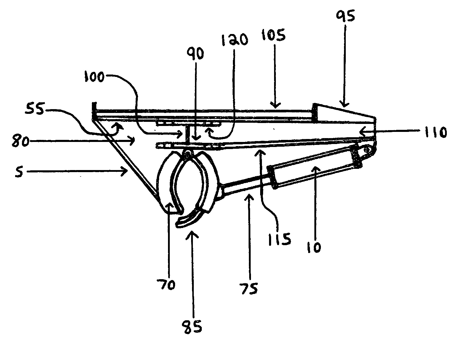
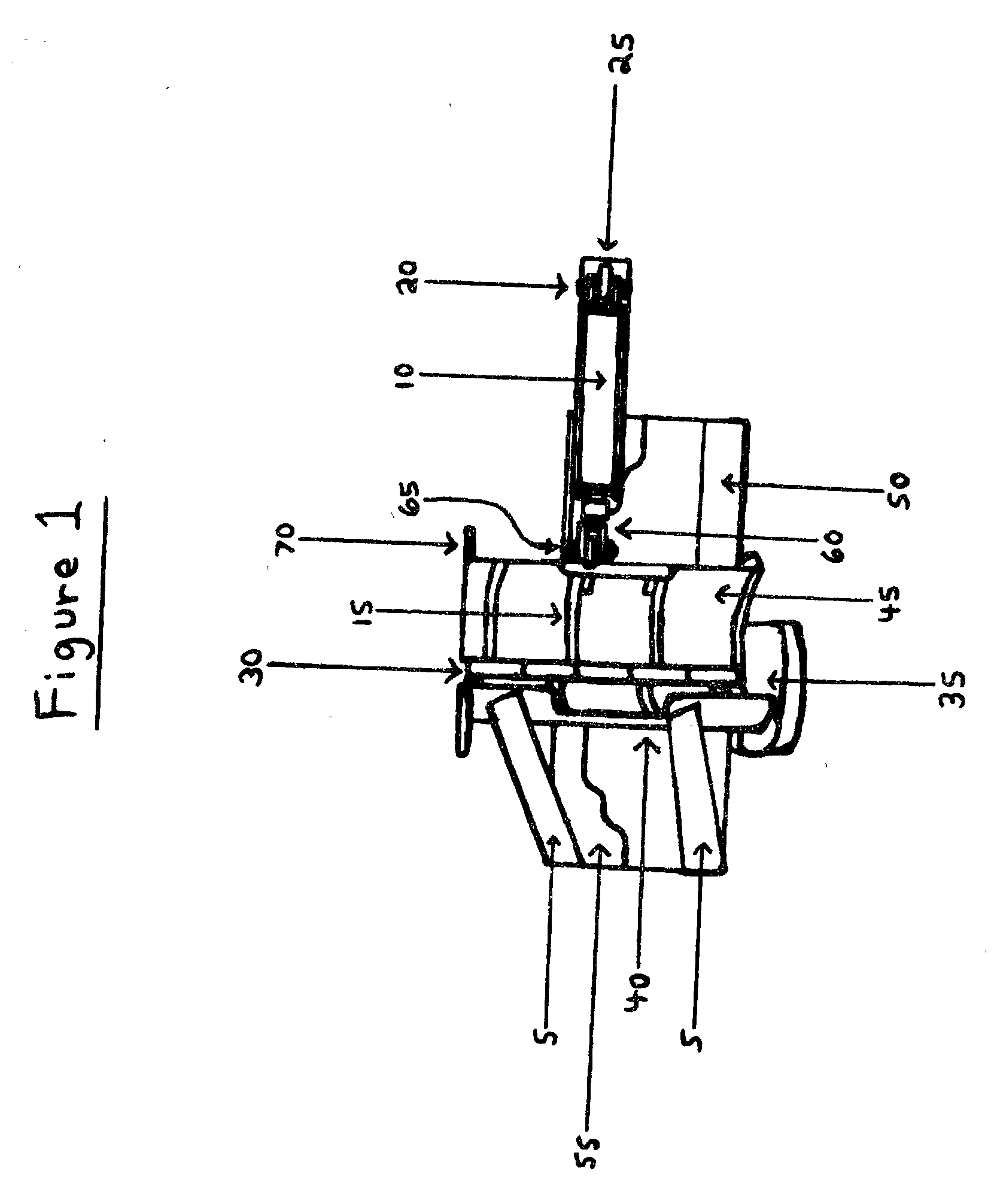
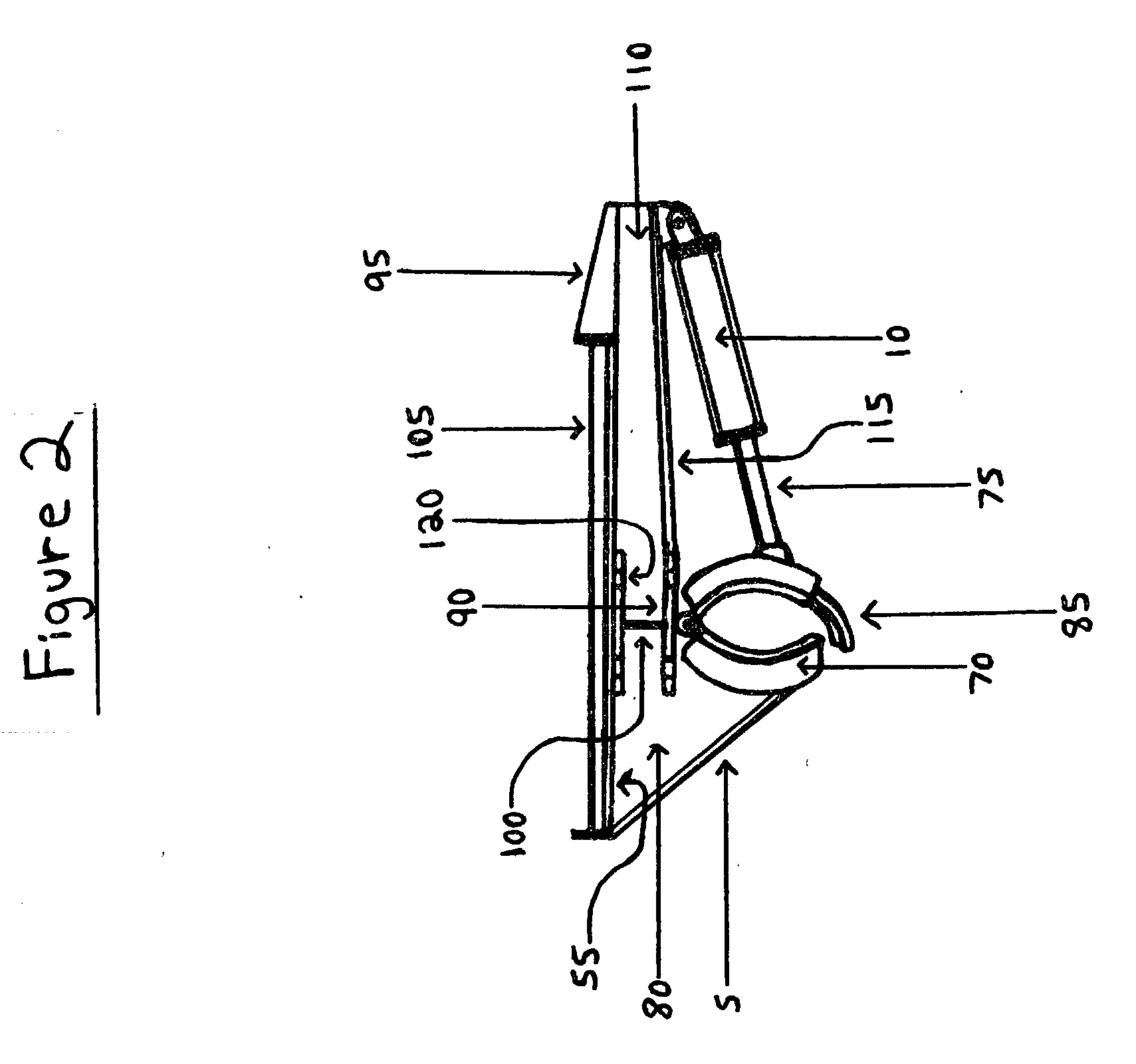
[0007] FIGS. 1 through 3 illustrate the preffered embodiment of the present invention.

[0008] As illustrated, the Hydraulic Operated Piling Grabber, which incorporates the unique Left jaw half closing mechanism (45) which is illustrated in FIG. 1. When the Cylinder (10) is hydraulically operating it will close Left Jaw Half (45) against Welded Right Jaw Half (40) which will Excert Pressure on the Piling being gripped. The inside wall of the Left and Right jaw halves are lined with hardened steel grips (15) to bite into the Piling for a very firm grip. The Welded Right Jaw Half (40) is supported by two angled plates (80) Top and Bottom, and also two Welded supports (5) Top and Bottom. The Cylinder Rod (75) of the Hydraulic Cylinder (10) is attached to the Left Jaw Half (45) by a bolt W / Lock Nut (65) to Welded Piece (25) by means of the Cylinder Mounting Bracket (60). The entire mechanism is Welded to the Bottom Frame Plate (50) and the Top Frame Plate (55) and also the Frame Right Sid...


PUM


Abstract

A versatile piece of hydraulically operated equipment for the use of handling and placement of wooden pilings for construction of foundation slabs in rear yards. With minimum access for house additions, able to grab, lift, and carry for placement of pilings for house additions, camps, bulkheads, or any foundation construction. Able to grab, lift, handle, and maneuver pilings of twenty, thirty, or forty feet in length, around trees, houses, under power lines or other obstacles to reach the desired position in any environment to place and shove pilings into specific pre-drilled holes, and drive pilings to desired elevations for construction site. An innovation in the placement of pilings in normally inaccessable areas which cannot be accomplished by present equipment available.

Description

[0001] 1. Field of the Invention[0002] The present invention relates to an improved way for the handling and driving of pilings for Slabs, Camps, Piers, Etc. . . . more particulary, the present invention relates to the lifting, handling, and driving of wooden pilings with a length of 30' or more, to place and insert into 8' Pre-drilled holes and then squeezed and shoved down into the ground to a specific grade for Concrete House Slabs, Commercial building Slabs, above ground Camps, Piers, Utility Poles etc.[0003] 2. General Background[0004] Pilings have been used for a long time to support foundations such as Slabs, and to prevent these foundations from sinking due to soft subsiding ground. Pilings have generally been driven with the use of large cranes which can cause damage to existing homes, they need large access, plenty of clearence from overhead power lines, and do not have the access to Back-Yards for Additions to existing homes.3. SUMMARY OF THE INVENTION[0005] The Present I...

Claims


Application Information

Patent Timeline
22 Apr 2004
Publication
US20040075289A1
IPC
B66C1/42; E02D27/48
CPC
E02D27/48; B66C1/427
Inventors
KING, LOUIS EDWIN