Laser System for Non-Contact and Selective Removal of Corrosion from Tubes Internal Surfaces

a laser cleaning and non-contact technology, applied in the field of contactless laser cleaning system, can solve the problems of reducing equipment efficiency and waste of revenue, increasing heat transfer loss in dirty tubes, and accumulating soot and corrosion damage quickly in the tubes, etc., to achieve the effect of minimal maintenance requirements, convenient use and reliability

Pending Publication Date: 2022-04-21
INNOVANEER INC
View PDF2 Cites 2 Cited by
  • Summary
  • Abstract
  • Description
  • Claims
  • Application Information

AI Technical Summary

Benefits of technology

[0049]The present invention aims at providing an easy, safe and cost-effective novel cleaning solution for industrial structures and equipment as an alternative to the labor intense, hazardous, and mechanical integrity impacting methods.
[0055]An objective of the present invention is to provide a method which renders it possible to remove oxides and any other buildups from metallic tube internal wall surfaces with a degree of reliability significantly higher than prior art methods, e.g. sand blasting, hydro blasting, and / or a combination of such conventional techniques.
[0056]Another objective is a cleaning system and method comprising a Fiber optic laser, which has the advantages of minimal maintenance requirements compared to other lasers, the ease of use, and environmentally friendly.
[0057]Another objective is to improve the safety wherein the system is able to perform non-contact cleaning or laser ablation of Oil & Gas, Chemical and other energy industrial tubular equipment, without the need to shut down or require lengthy downtime for tube.
[0058]Another objective to provide a cleaning system that is intrinsically safe by reducing or eliminating internal sparking, controlling temperature, and eliminating component spacing to block dust collection.

Problems solved by technology

During the operational life cycle of reactors and heat-exchangers, no matter what type of fuel or chemical product is used, soot and corrosion damage will quickly accumulate in the tubes.
This buildup reduces equipment efficiency and wastes of revenue.
The heat transfer loss in a dirty tube rises tremendously as the layer of soot builds up.
Over time, corrosion of the tubes can also be a cause of reduced tube efficiency or even tube failure.
The need for cleaning arises because the transported medium can cause deposits, which build up in the tubes and cause obstructions.
It is also one of the most difficult as excessive cleaning may affect the integrity of the cleaned objects.
While the passive protection of a coating system solves corrosion / erosion problems, reports show that thin film coatings of 25 to 80 millimeters have failed due to improper application, and because a thin film thickness is insufficient to withstand the long-term abuse of cooling water systems, such as from the impact during the mechanical cleanings and inspections.
Counter productively, a partially failed coating may accelerate galvanic attack.
Also, several tube-ends can be deformed by the improper use of high-pressure water blasting, which is used to clean the tube sheets; as a result, severe joint leaks may be created.
All categories of in-water cleaning methods have the potential to damage antifouling coatings, and make the assessment of damage complicated.
There is, however, potential for damage if the equipment is not used appropriately.
Although the applied pressure may be lower during in-water cleaning, a high-pressure jet held close to and directly on a surface for too long will erode ablative or self-polishing the exposed metal.
Additionally, a corkscrew pattern could be left behind from high-pressure cleaning, and this is typically due to the cleaning tip of the cleaning tool travelling too quickly.
However, this technique is not popular and requires further investigation in terms of required downtime of equipment, cost analysis, and applicability in the field.
While thermal decomposition is effective, it is not applicable to every heat exchanger.
Depending on the fouling level, the type of service and how quickly the facility needs the equipment back, thermal decomposition might not be the right choice.
The choice of a cleaning process to use in corrosion removal or conservation is frequently complicated by questions, such as ‘what will be removed?’ or ‘what will be preserved?’.
However, the results are often strongly dependent upon the skill and experience of the individual operator since all effective cleaning processes can cause some degree of damage if incorrectly used.
In practice, it is rarely possible to entirely separate the contaminants from the object.
Even if mechanical cleaning is carried out with care, techniques such as blasting will always result in some loss of material from a surface, particularly from a crumbling decayed surface, simply because abrasive particles cannot discriminate between the dirt and the substrate.
The loss of surface can reduce the thickness and in extreme cases can even lead to deterioration of the material.
Also, chemical-based cleaning techniques leave residues within the material which can cause long-term problems.
Lasers can remove unwanted layers that conventional techniques cannot remove safely.
Because the corrosion products are usually mixed in with the original material, it is often difficult to distinguish between them.
However, lasers have a large initial investment cost, which is the main disadvantage of this technique.
They are bound by strict water usage laws that can come with stiff penalties, the water usage requirements of high-pressure water cleaning have made this approach unviable.
These conventional manual methods are problematic when associated to the mechanical damage and / or hazardous environment for the operator, especially when parts of the structure to evaluate and maintain are located at heights.
In addition, these manual methods cause downtime to parts of the production facilities that are under evaluation.
The type of deposits, their tenacity to adhere to the tube walls and their insulating value depend on the fluids or gases flowing within the tubes, and the result of their presence is a loss in productivity.

Method used


Image

  • Laser System for Non-Contact and Selective Removal of Corrosion from Tubes Internal Surfaces
  • Laser System for Non-Contact and Selective Removal of Corrosion from Tubes Internal Surfaces
  • Laser System for Non-Contact and Selective Removal of Corrosion from Tubes Internal Surfaces

Examples


example 1

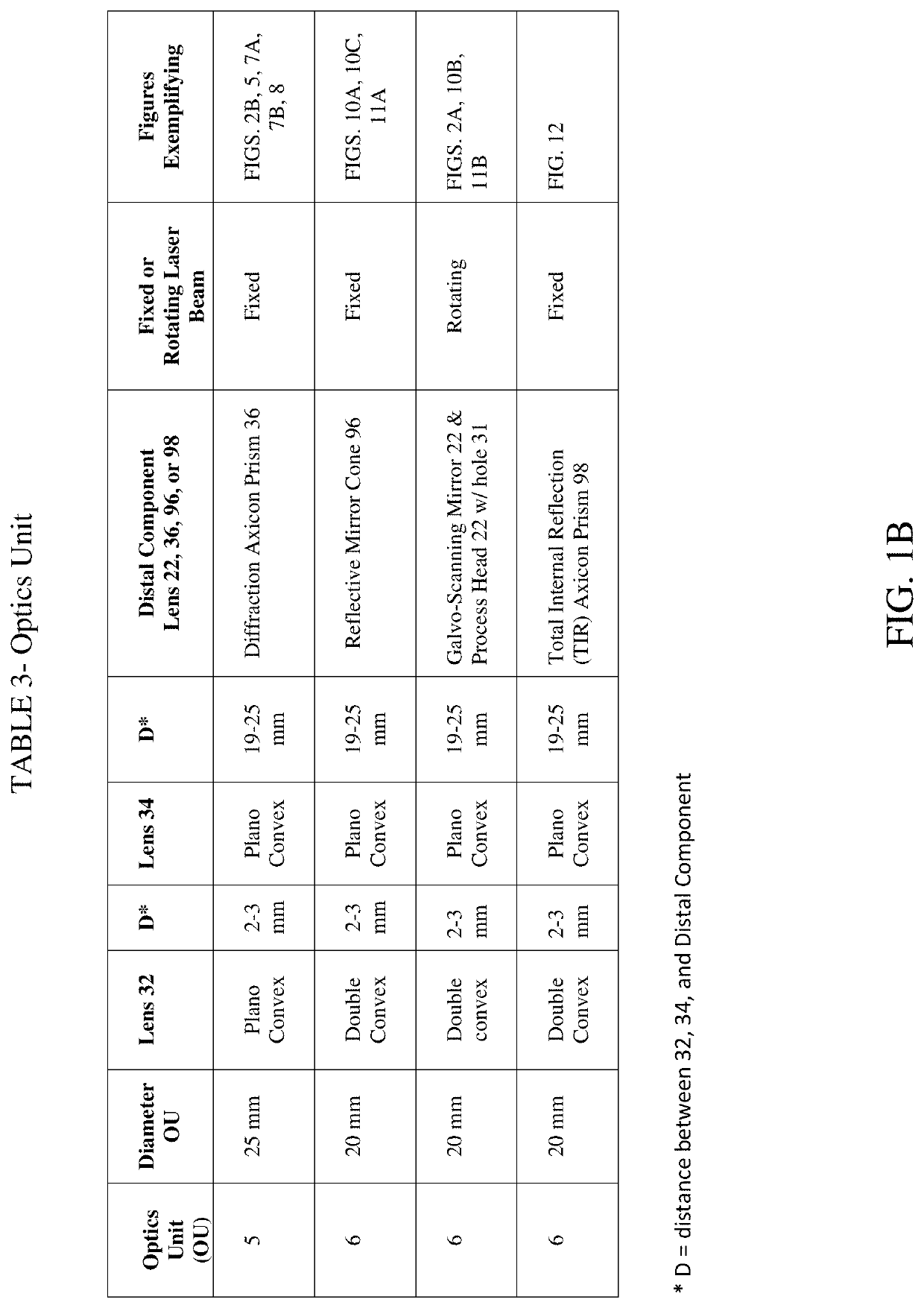
[0122]An experiment was performed using the laser cleaning system of FIG. 8 comprising: two plano-convex lens 32, 34 with curves facing, and a Diffraction Axicon lens 36. The beam parameter (min) is 25 mm (lens 32), 24.4 mm (lens 34), and 12.8 mm (lens 36). Table 4 show irradiance parameters with respect to sampled tube 9 inner diameters; ‘39, 42, and 45 mm’. It is based on a design with the focusing option of axicon parameters; with apex angle 90 degrees, and the axicon surface is turned to the lenses side.

TABLE 4Tube DiameterTube DiameterTube DiameterLEVEL39 mm42 mm45 mm0.5 max 0.6 mm0.68 mm0.68 mm0.1 max1.25 mm1.36 mm1.35 mm

[0123]Referring FIGS. 13A-13C: are graphs of the Incoherent Irradiance in watts / cm2 (y-axis) versus the width of the illuminated laser ring at the tube surface in millimeters (mm) at three different tube diameters: tube diameter 39 mm (FIG. 13A), 42 mm (FIG. 13B), and 45 mm (FIG. 13C), respectively. Results demonstrate that the width of illuminated laser ring ...

example 2

[0124]Another experiment was performed using the laser cleaning system of FIG. 12 comprising optics unit 6: a double convex lens 32, a plano-convex lens 34 with curves facing, and an TIR Axicon lens 98. The beam parameter (min) is 16.8 mm (lens 32), 16.4 mm (lens 34), and 9.3 mm (lens 98). Table 5 is shows irradiance parameters with respect to sampled tube 9 inner diameters; ‘39, 42, and 45 mm’.

TABLE 5Tube DiameterTube DiameterTube DiameterLEVEL39 mm42 mm45 mm0.5 max0.19 mm0.19 mm0.27 mm0.1 max0.45 mm0.27 mm0.50 mm

[0125]Referring FIGS. 14A-14C: are graphs of Incoherent Irradiance in watts / cm2 (y-axis) versus the width of the illuminated laser ring at the tube surface in millimeters (mm) at three different tube diameters: tube diameter 39 mm (FIG. 14A), 42 mm (FIG. 14B), and 45 mm (FIG. 14C), respectively. Results demonstrate that the width of illuminated laser ring at the tubes 9 inner surface 24 ranges from 0.19 to 0.27 mm at half maximum. And it ranges between 0.27 to 0.5 mm at 10...


PUM

PropertyMeasurementUnit
areaaaaaaaaaaa
output poweraaaaaaaaaa
distanceaaaaaaaaaa

Abstract

An automated or manual laser ablation system and method of use to enable safe, non-user-contact, rapid, and remote cleaning of industrial tubular equipment, e.g. heat-exchangers and reactors. The laser ablation system comprises: a fiber optic cable (12) with a laser probe output end (20), connected to an optics unit (5 or 6) enclosed within a laser probe housing (14). The optics unit comprises: a double convex and / or one or two plano-convex lens; and an Axicon prism, mirror cone, and / or galvo-scanning mirror to emit a rotating or a fixed circular beam. The laser beam cleans a plurality of reactor tubes' internal wall to cause the evaporation of deposit buildups and rust. The laser ablation system further comprises: an air vacuum system (30) positioned to cool the ablation system while removing the debris to a vacuum generator (35); and / or a push motor (60) that pushes and pulls the system through the tubes.

Description

FIELD OF THE INVENTION[0001]The present invention relates to a contactless laser cleaning system for tubes within a reactor and / or a heat exchanger requiring no user-contact with the tubes, laser, or cleaning debris.BACKGROUND OF THE INVENTION[0002]During the operational life cycle of reactors and heat-exchangers, no matter what type of fuel or chemical product is used, soot and corrosion damage will quickly accumulate in the tubes. According to a case study performed by M&D Advance Technology, which is a company that specializes in traditional tube cleaning services, as much as ⅛ inch of soot can build up in only two weeks. This buildup reduces equipment efficiency and wastes of revenue. Soot has five times the insulating value of asbestos. The heat transfer loss in a dirty tube rises tremendously as the layer of soot builds up. Equipment efficiency can be monitored through stack temperature readings, the measure of temperature of gases when they leave boiler tubes group. For every...

Claims


Application Information

Patent Timeline
Patent Type & Authority Applications(United States)
IPC IPC(8): B08B7/00B08B9/051B08B9/049B08B5/04F28G15/04B23K26/06B23K26/03B23K26/08B23K26/36B23K26/16
CPCB08B7/0042B08B9/051B08B9/0492B08B5/04F28G15/04B23K26/0643B08B2209/04B23K26/0652B23K26/032B23K26/0869B23K26/36B23K26/16B23K26/0648B23K26/082B23K26/0096B08B9/045F28G1/00
Inventor MATTAR, RAMI
Owner INNOVANEER INC
Why Eureka
Try Eureka