

Pump capable of releasing excessive air
a technology of excessive air and pressure, applied in the field of pressure, can solve the problems of inconvenient removal of the nozzle 90 from the tire valve, inability to release excessive air from the tire, and render precise pumping more difficult, etc., and achieve the effect of convenient operation and convenient touch
- Summary
- Abstract
- Description
- Claims
- Application Information
AI Technical Summary
Benefits of technology
Problems solved by technology
Method used
Image

Examples
Embodiment Construction
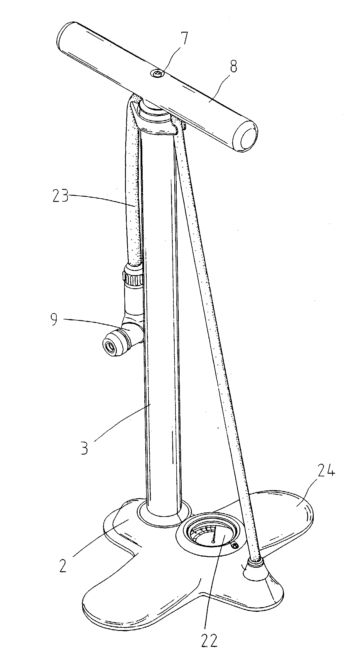
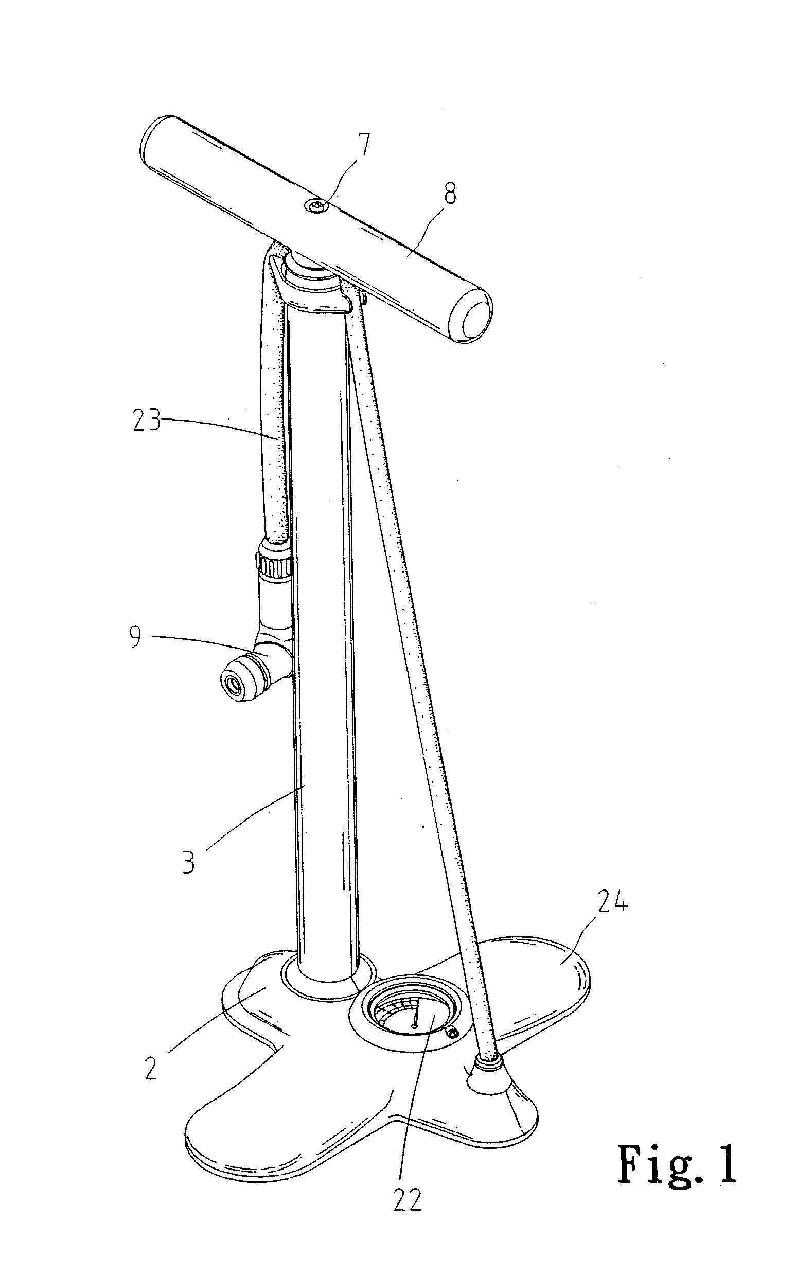
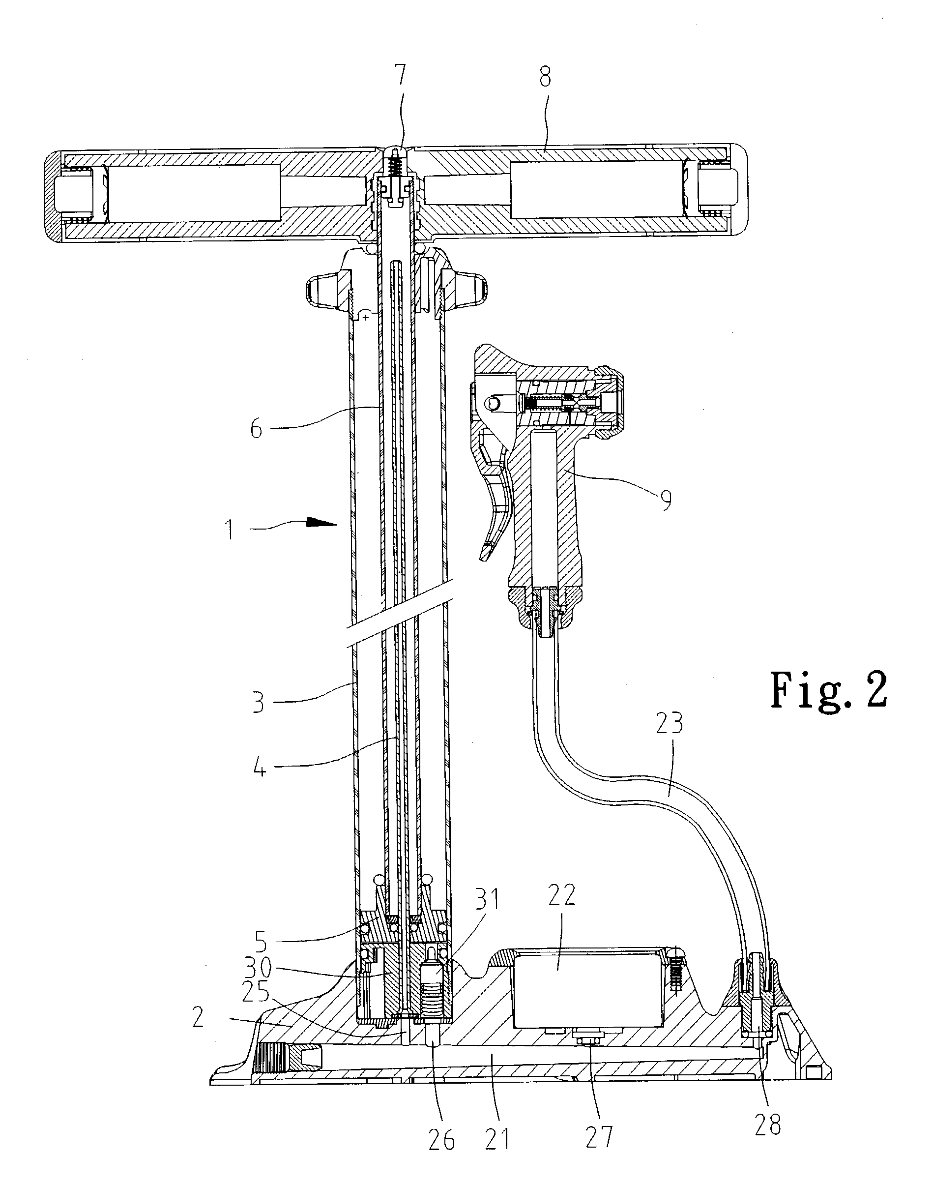
[0015] Referring to FIGS. 1 and 2, according to the preferred embodiment of the present invention, a pump 1 capable of releasing excessive air is shown to include a hollow base 2, a cylinder 3 installed on and communicated with the hollow base 2, a piston 5 movably received in the cylinder 3, a piston tube 6 including a lower end connected with the piston 5 and an upper end located beyond the cylinder 3, a tube 4 including a lower end communicated with the hollow base 2 and an upper end inserted into the piston tube 6 through a channel (not numbered) defined in the piston 5, a release valve 7 mounted on the upper end of the piston tube 6 and a handle 8 mounted on the upper end of the piston tube 6. The valve 7 is installed on the handle 8 so that it can be touched conveniently and operated easily by a user who is using the pump 1.
[0016] The base 2 includes two treads 24 on which the user can set his or her feet in order to hold the pump 1 still. The base 2 defines a trunk channel 21...
PUM
 Abstract
Description
Claims
Application Information