

Vehicle seat air conditioning system
a technology for air conditioning systems and seats, applied in the direction of chairs, transportation and packaging, vehicle arrangements, etc., can solve the problems of unfavorable design and uncomfortable feeling of surface cover material, and achieve the effect of not making undesirable dent in the design
- Summary
- Abstract
- Description
- Claims
- Application Information
AI Technical Summary
Benefits of technology
Problems solved by technology
Method used
Image

Examples
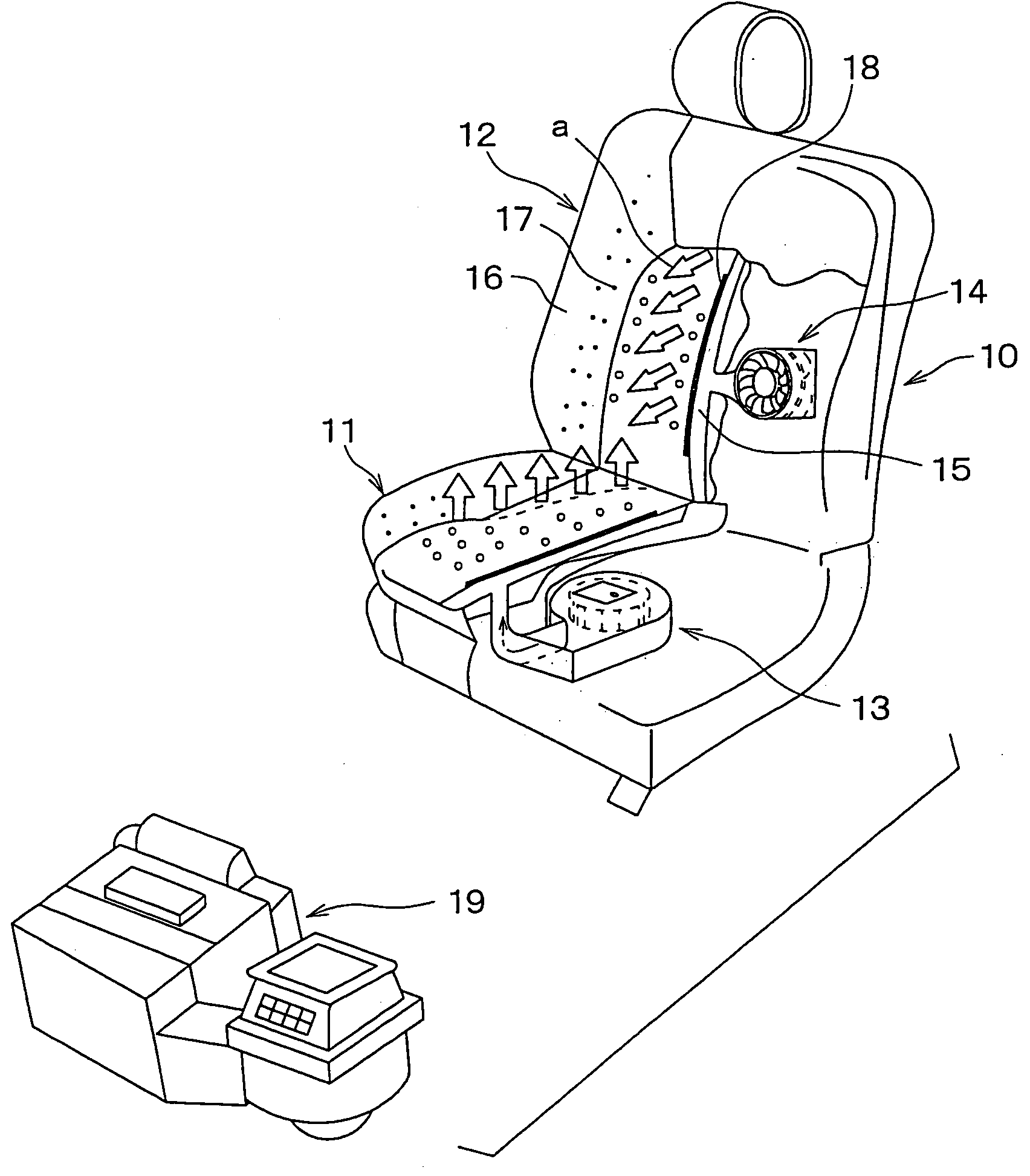
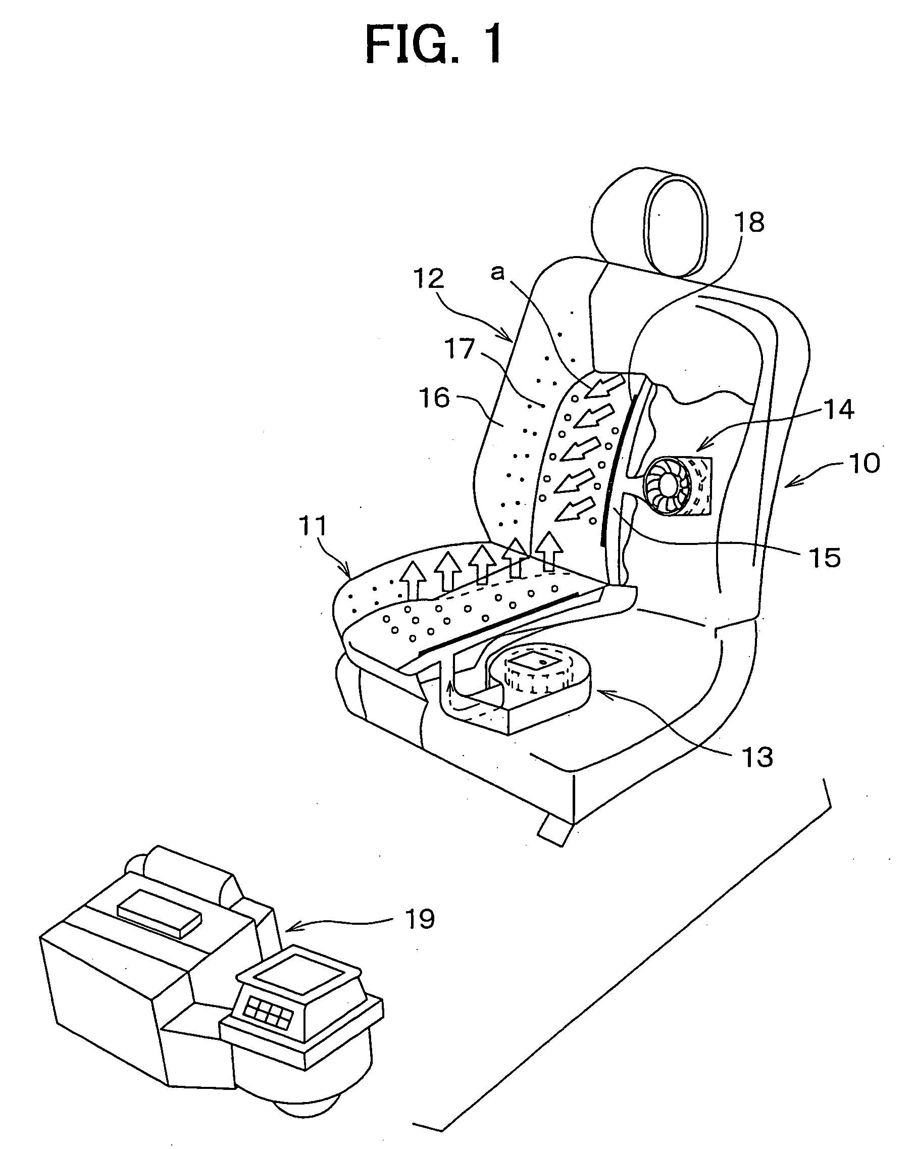
first embodiment
[0064] Now, the above function and effects will be summarized.
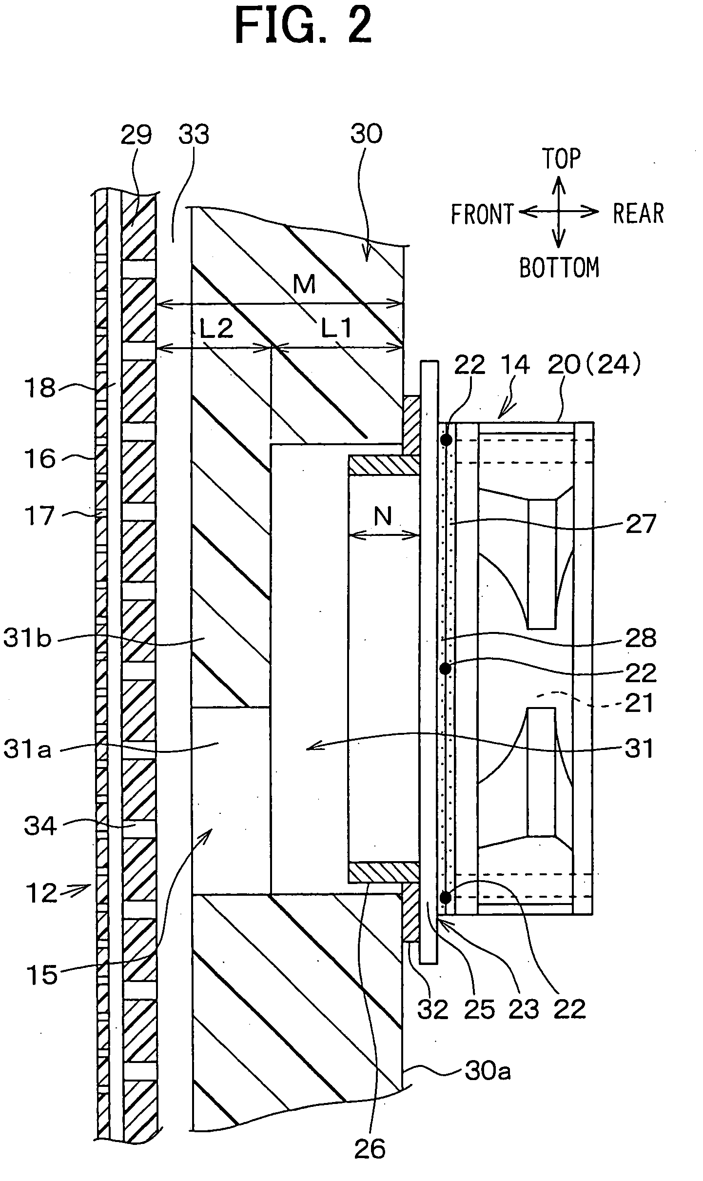
[0065] (1) The use of the support portion 31b formed integrally with the cushion member 30 removes the necessity of a rigid cover member. Therefore, a passenger does not feel discomfort that would otherwise be caused in seating because of the presence of the cover member.
[0066] (2) The cross-sectional area of the air-blowing hole 31 is approximately equal to or larger than the blade size D2 of the air-blowing fan 21. Therefore, when air is blown by the second air-blowing unit 14, the airflow resistance can be reduced, which secures the air blowing performance.
[0067] (3) The cross-sectional area of each of the hole portions 31a is smaller than the cross-sectional area of the air-blowing hole 31, and there are a number of such hole portions. Therefore, the strength of the support portion 31b can be maintained, while the airflow resistance can be restrained.
[0068] (4) The electric heater 18 is provided on the back side of t...
second embodiment
[0069] According to the first embodiment, the air blowing casing 20 and the attachment bracket member 23 at which the inlet duct portion 26 is provided are joined together with bolts (not shown). Then, the inlet duct portion 26 is inserted into the air-blowing hole 31. Meanwhile, according to a second embodiment, as shown in FIG. 5, in place of the attachment bracket member 23, an air outlet portion 35 provided with holes in the center for supplying air is used. On the backside of the cushion member 30, a protrusion 30b protruding toward the air-blowing unit 14 is provided over the entire circumference from the opening of the air-blowing hole 31. The air outlet portion 35 is fitted with the protrusion 30b. In this manner, the second air-blowing unit 14 is inserted as it is surrounded by the protrusion portion 30b, and therefore air blown from the second air-blowing unit 14 is kept from leaking through the air-blowing hole 31.
third embodiment
[0070] As shown in FIG. 6, the hole portions 31a may be a plurality of triangular shapes. The hole portions 31a are in communication with the air distribution groove 33.
PUM
 Abstract
Description
Claims
Application Information