Safety shield for medical needles

a shield and needle technology, applied in the direction of guide needles, needles for infusion, catheters, etc., can solve the problems of high cost, difficulty in properly disposing of used needles, and high difficulty in us

Inactive Publication Date: 2004-05-13
SPECIALIZED HEALTH PRODS
View PDF99 Cites 88 Cited by
  • Summary
  • Abstract
  • Description
  • Claims
  • Application Information

AI Technical Summary

Problems solved by technology

Under such conditions, it is difficult to properly dispose of a used needle while caring for a patient.
Problems of current safety devices include difficulty of use and high cost due to their complexity and number of parts.
These devices, however, may disadvantageously misfire or be cumbersome to activate.
Further drawbacks of current devices include high manufacturing cost due to complexity and the number of parts.
Thus, these type prior art devices may not adequately and reliably shield medical needle apparatus to prevent hazardous exposure.

Method used


Image

  • Safety shield for medical needles
  • Safety shield for medical needles
  • Safety shield for medical needles

Examples


Embodiment Construction

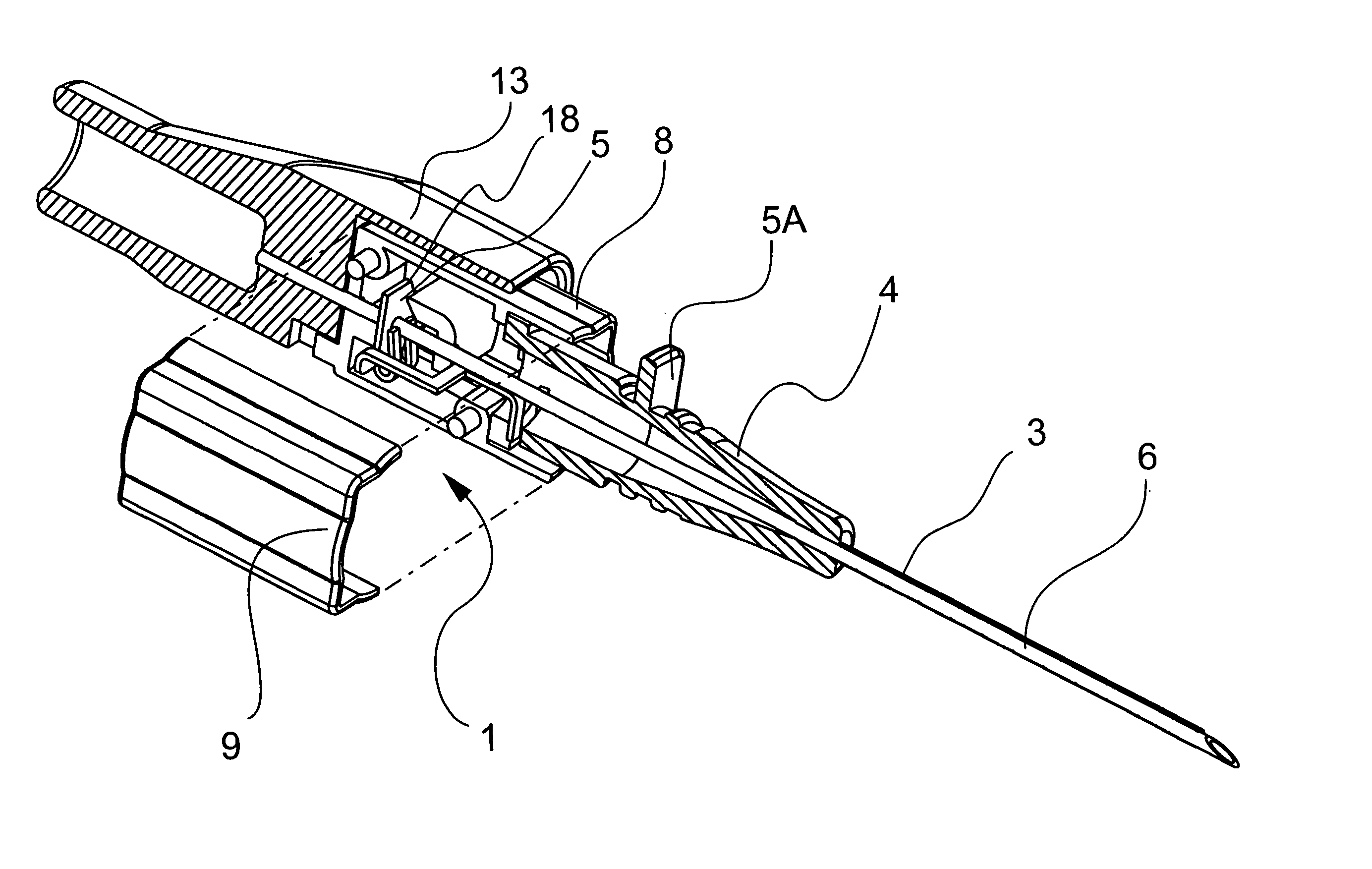
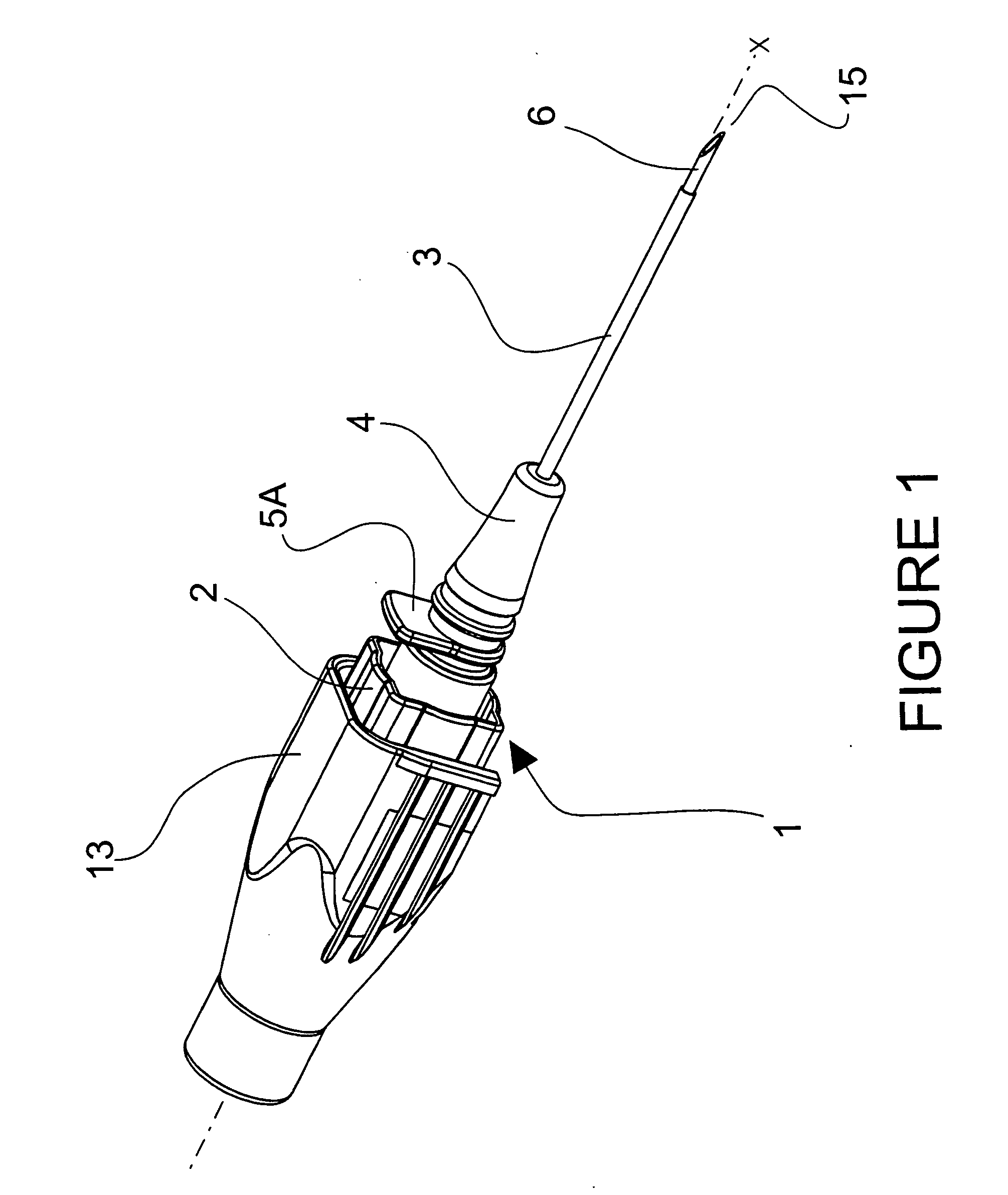
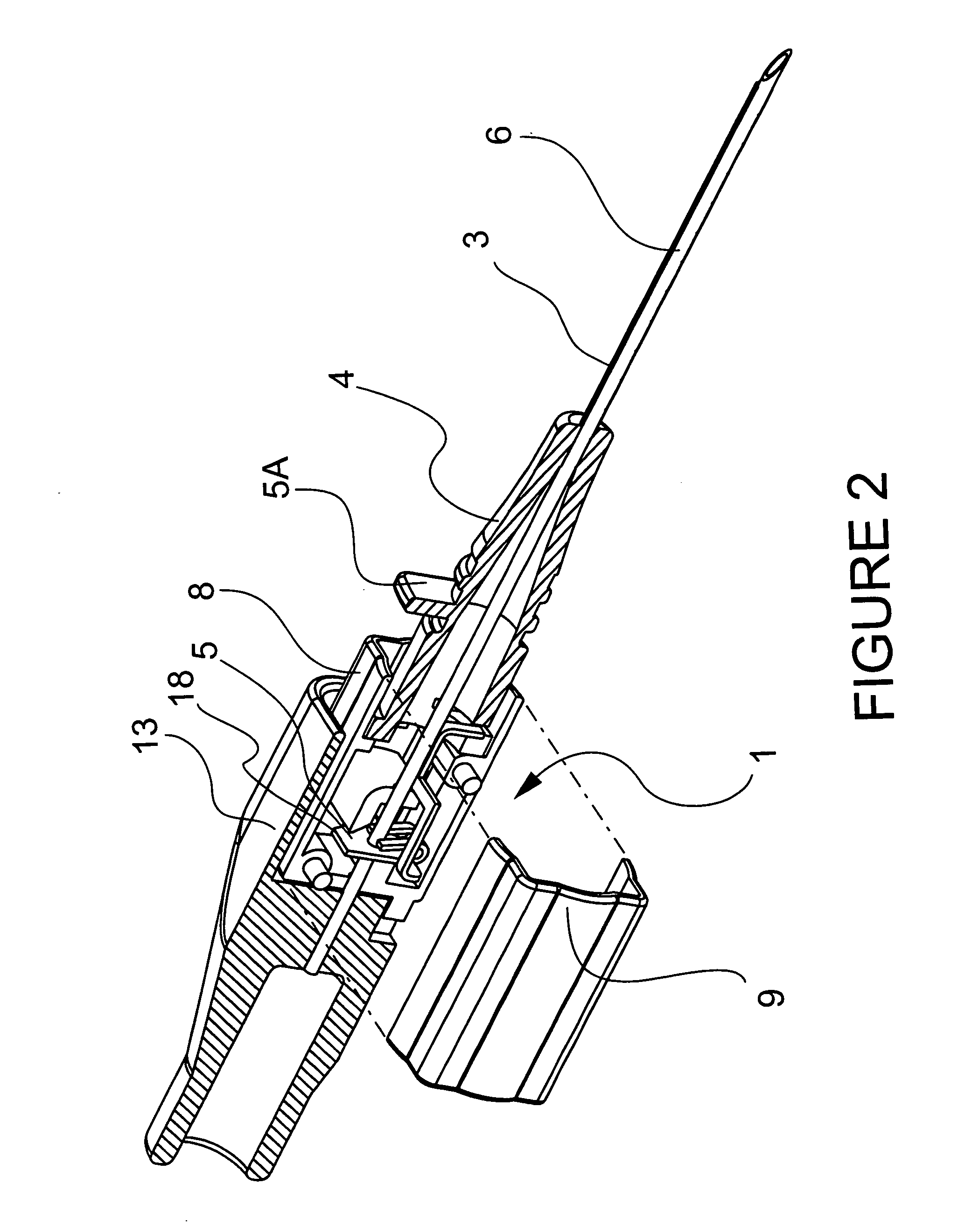
[0069] The exemplary embodiments of the medical needle shield apparatus and methods of operation disclosed are discussed in terms of medical needles for infusion of intravenous fluids, medication infusion or fluid collection, and more particularly, in terms of needle shield apparatus employed with a needle cannula that prevent hazardous exposure to a needle tip, including, for example, inadvertent needle sticks. It is contemplated that the medical needle safety shield apparatus may be utilized for medical needle applications including, but not limited to, fluid infusion, fluid collection, catheters, catheter introducers, guidewire introducers, spinal and epidural, biopsy, aphaeresis, dialysis, blood donor, Veress needles, Huber needles, winged ("butterfly") needles, etc. It is envisioned that the present disclosure, however, finds application to a wide variety of cannula needles and devices for the infusion of preventive medications, medicaments, therapeutics, etc. to a subject. It ...


PUM


Abstract

A medical needle shield apparatus including a shield that is extensible from a retracted position to an extended position to enclose a distal end of a needle. A binding member is disposed within the shield and defines binding surfaces that form an aperture configured for slidable receipt of the needle between the retracted position and the extended position. The binding member includes drag inducing members disposed thereon that engage the needle during slidable receipt of the needle to create a drag force with the needle. The drag force facilitates rotation of the binding member relative to a longitudinal axis of the needle such that the binding surfaces engage the needle to prevent slidable movement of the needle in the extended position of the shield. The binding member further includes a retainer extending therefrom such that the retainer is engageable with the needle to prevent rotation of the binding member prior to the extended position. The shield further includes a hub retainer for releasable attachment to a catheter hub.

Description

[0001] This patent application is a continuation-in-part of U.S. Utility patent application Ser. No. 10 / 409,819, filed in the U.S. Patent and Trademark Office on Apr. 8, 2003 by Ferguson et al., which claims priority to U.S. Utility patent application Ser. No. 10 / 322,288, filed in the U.S. Patent and Trademark Office on Dec. 17, 2002 by Ferguson et al., and U.S. Provisional Patent application Serial No. 60 / 424,655, filed in the U.S. Patent and Trademark Office on Nov. 7, 2002 by Bagley et al., and U.S. Utility patent application Ser. No. 10 / 202,201, filed in the U.S. Patent and Trademark Office on Jul. 23, 2002 by Ferguson, which is a continuation-in-part of U.S. Utility patent application Ser. No. 09 / 809,357, filed in the U.S. Patent and Trademark Office on Mar. 15, 2001 by Ferguson et al., the entire contents of each of these disclosures being hereby incorporated by reference herein.[0002] 1. Technical Field[0003] The present disclosure generally relates to safety shields for medi...

Claims


Application Information

Patent Timeline
Patent Type & Authority Applications(United States)
IPC IPC(8): A61M5/158A61M5/32A61M25/06
CPCA61M5/3273A61M2005/325A61M25/0618
Inventor FERGUSON, F. MARKTHORNE, DAVID L.SOLOMON, DONALD D.SMITH, DANIEL K.SNOW, JEREMY W.BAGLEY, B. CHANCETHOME, CRAIG N.
Owner SPECIALIZED HEALTH PRODS
Why Eureka
Try Eureka