Custom replacement device for resurfacing a femur and method of making the same

a replacement device and femur technology, applied in the field of knee joint replacement devices, can solve the problems of degenerative arthritis, tracking problems, and patella dislocation or slippage, and achieve the effects of improving the quality of li

Inactive Publication Date: 2004-05-20
KINAMED
View PDF18 Cites 329 Cited by
  • Summary
  • Abstract
  • Description
  • Claims
  • Application Information

AI Technical Summary

Problems solved by technology

For example, the patella may dislocate or slip out of place, it may fracture, or develop a tracking problem.
A tracking problem occurs when the patella no longer remains centered within the groove as it glides over the femur.
The resulting abnormal biomechanics can cause chronic pain in the joint and if left untreated, it can lead to degenerative arthritis.
When this cartilage breaks down, the cushion is lost, resulting in pain, swelling, bone spur formation and / or decreased range of motion of the knee joint.
Due to the inability of damaged cartilage to repair itself after injury, the range of treatment for patients with unicompartmental disease involving the patella is limited.
In certain instances none of these procedures may be desirable or effective.
For example, the soft tissue procedures may not work.
A patient having undergone a patellectomy is left partially crippled due to the loss of the kneecap, which served to hold the joint together.
Additionally, these patients often still suffer from pain due to contact of the remaining tendon moving directly over the groove.
A total knee replacement with a standardized prosthesis is also far from ideal because much of the femur bone must be carved away in order to "fit" the distal surface of the femur to the standardized prosthesis.
Additionally, the patients are often young and are likely to require replacement of the prosthesis.
Each revision operation is more difficult.

Method used


Image

  • Custom replacement device for resurfacing a femur and method of making the same
  • Custom replacement device for resurfacing a femur and method of making the same
  • Custom replacement device for resurfacing a femur and method of making the same

Examples


Embodiment Construction

[0029] This description is not to be taken in a limiting sense, but is made merely for the purpose of illustrating the general principles of the invention. The section titles and overall organization of the present detailed description are for the purpose of convenience only and are not intended to limit the present invention.

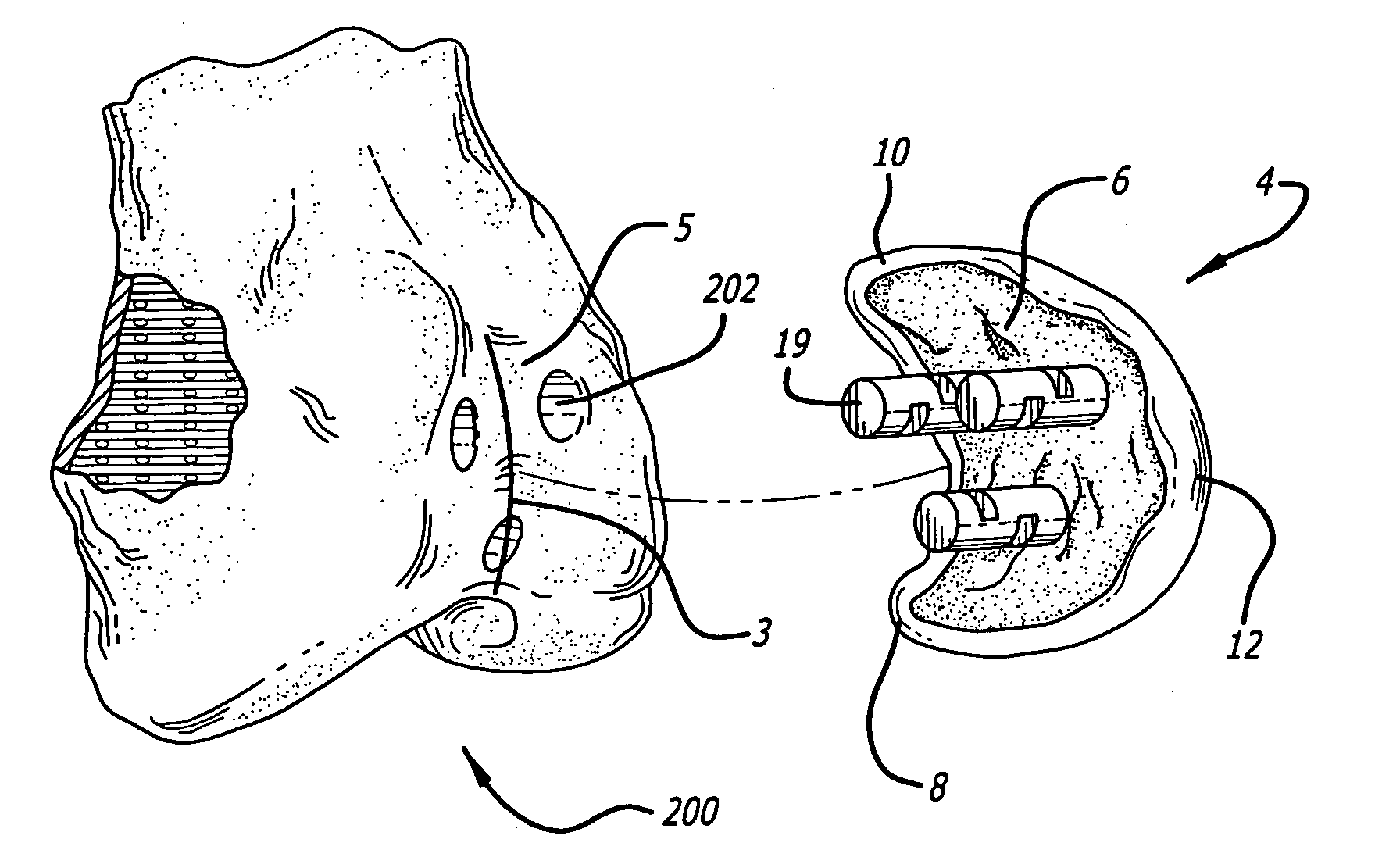
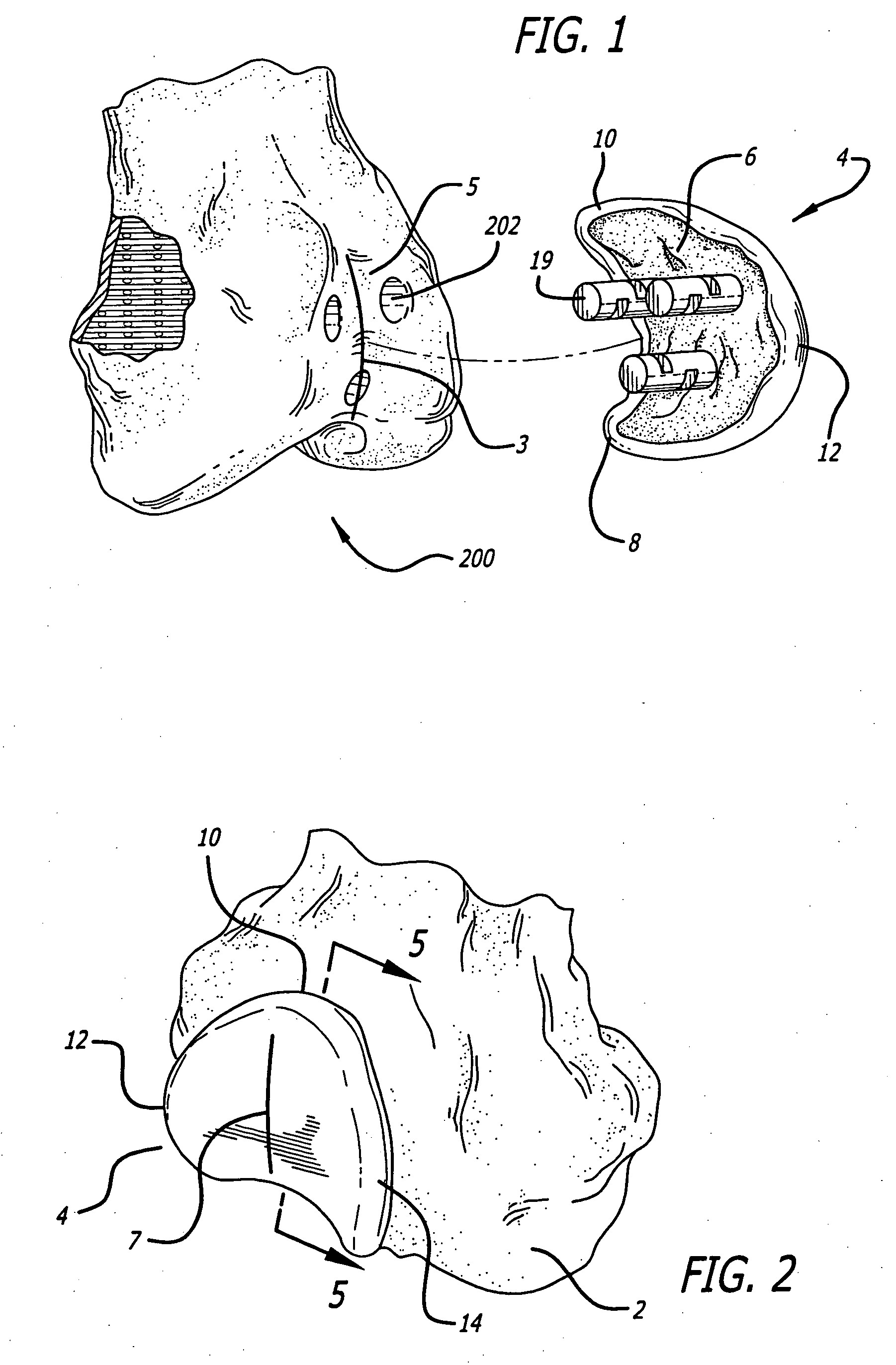
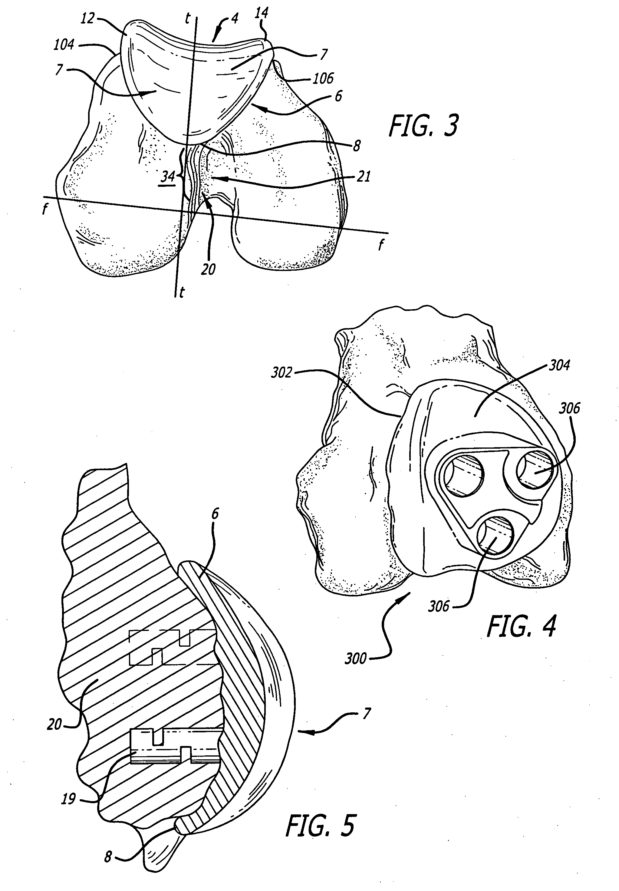
[0030] One of the features of the present invention is to provide a replacement device for a patient's knee joint that replicates as closely as possible the original kinematics of the patient's knee. More particularly, the replacement device substantially replicates patient's actual trochlear tracking pattern of the femur to maintain the original articulating movement of the knee. To do so, unhealthy articular cartilage is removed and replaced with the replacement device, which is custom fitted for a patient's femur to maintain as closely as possible the original articulating movement of the patella about the trochlear groove. That is, the replacement device is...


PUM

PropertyMeasurementUnit
thicknessaaaaaaaaaa
thicknessaaaaaaaaaa
distanceaaaaaaaaaa

Abstract

A replacement device for resurfacing a joint surface of a femur and a method of making and installing such a 5 device is provided. The custom replacement device is designed to substantially fit the trochlear groove surface, of an individual femur. Thereby creating a "customized" replacement device for that individual femur and maintaining the original kinematics of the joint. The replacement device may be defined by four boundary points, and a first and a second surface. The first of four points is 3 to 5 mm from the point of attachment of the anterior cruciate ligament to the femur. The second point is near the bottom edge of the end of the natural articulatar cartilage. The third point is at the top ridge of the right condyle and the fourth point at the top ridge of the left condyle of the femur. The top surface is designed so as to maintain centrally directed tracking of the patella perpendicular to the plane established by the distal end of the femoral condyles and aligned with the center of the femoral head.

Description

CROSS-REFERENCE TO RELATED APPLICATIONS[0001] This application is a divisional of U.S. application Ser. No. 09 / 528,128, filed Mar. 17, 2000, herein incorporated by reference in its entirety.BACKGROUND OF THE INVENTION[0002] 1. Field of the Invention[0003] The invention relates generally to a replacement device for a knee joint, and more particularly, to a device for resurfacing the trochlear groove of a femur that is customized to an individual and to methods for installing and making the same[0004] 2. Description of the Related Art[0005] The human knee joint primarily includes three parts, anatomically referred to as the femur (thighbone), the tibia (shinbone) and the patella (kneecap). The knee joint is then further subdivided into two joints: the patella-femoral joint (space between the kneecap and distal anterior surface of the thighbone) and the tibia-femoral (space between the thighbone and shinbone).[0006] During normal bending and straightening of the leg, the patella (kneec...

Claims


Application Information

Patent Timeline
Patent Type & Authority Applications(United States)
IPC IPC(8): A61B17/00A61B17/17A61F2/00A61F2/30A61F2/38
CPCA61B17/00491A61B34/10A61F2/30767A61F2/30942A61F2/3877A61F2002/30125A61F2002/30594A61F2002/30685A61F2002/30892A61F2002/30948A61F2002/30952A61F2002/30957A61F2230/0008A61F2310/00017A61F2310/00023A61F2310/00029A61F2310/00203A61F2310/00239A61F2310/00407A61F2310/00796Y10S623/901A61F2/3859A61F2/461A61F2/4657A61F2002/4658A61B2034/108Y10T29/49764A61B17/1764
Inventor CARIGNAN, ROGERPRATT, CLYDE R.
Owner KINAMED
Why Eureka
Try Eureka