Balanced amplifier and filter using the same

a technology applied in the field of balanced amplifier and filter, can solve the problems of differential pair not being able to exhibit sufficient performance, the maximum value of an output signal amplitude is too small, and the number of cascaded transistors which are stacked is limited

Inactive Publication Date: 2004-08-26
KK TOSHIBA
View PDF6 Cites 7 Cited by
  • Summary
  • Abstract
  • Description
  • Claims
  • Application Information

AI Technical Summary

Problems solved by technology

In such a conventional circuit, since the common-mode component removing property of the differential pair is used, the number of cascaded transistors which are stacked is limited, and the maximum value of an output signal amplitude is too small when this circuit operates at a low voltage.
When the power supply voltage further decreases in this manner, the differential pair cannot exhibit sufficient performance, i.e., a sufficient output amplitude cannot be obtained, when it is operated at the same voltage as that for the digital circuit.
Therefore, it may become difficult to obtain a sufficient noise removing effect even if a noise removing circuit is formed by using a balanced amplifier.

Method used


Image

  • Balanced amplifier and filter using the same
  • Balanced amplifier and filter using the same
  • Balanced amplifier and filter using the same

Examples


first embodiment

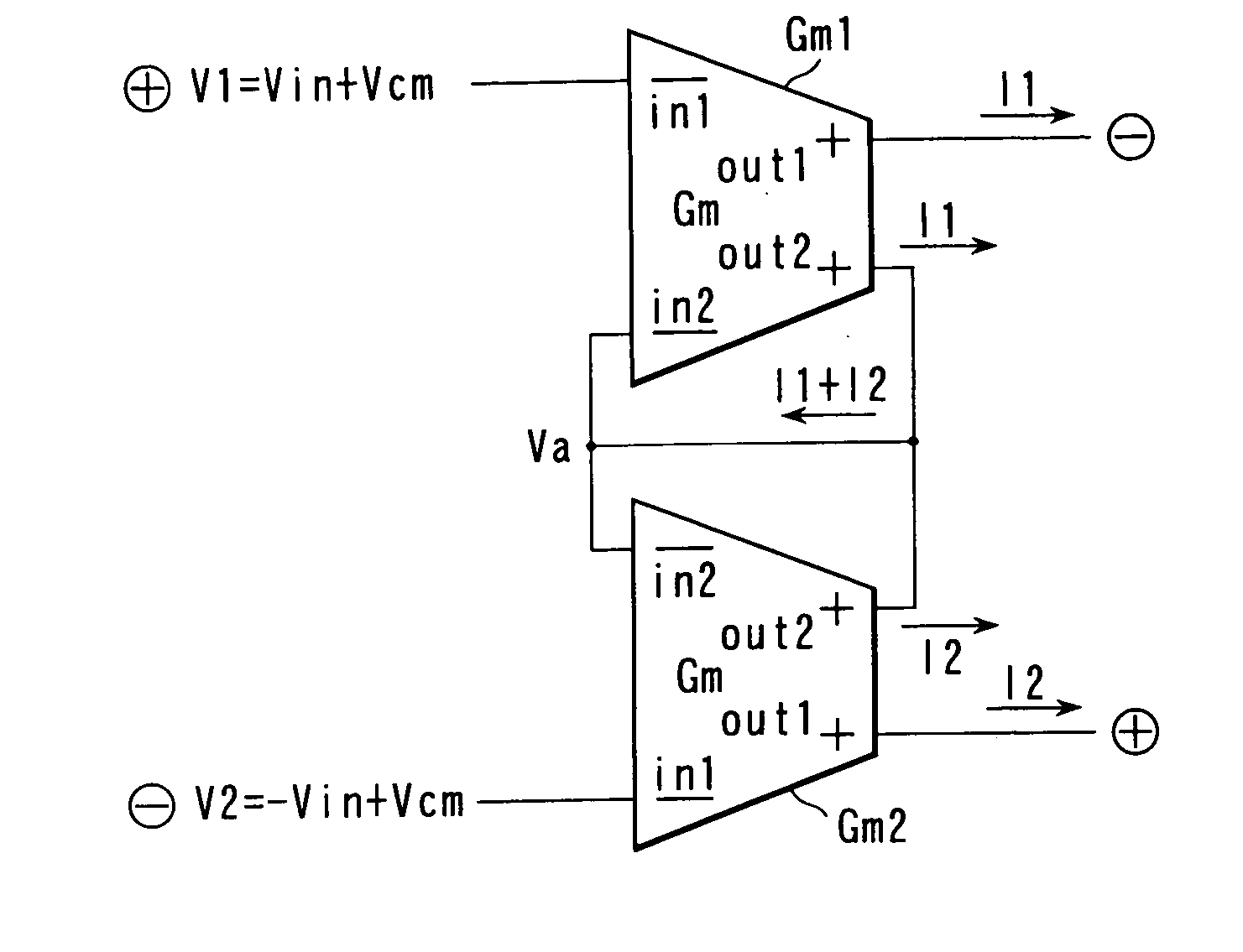
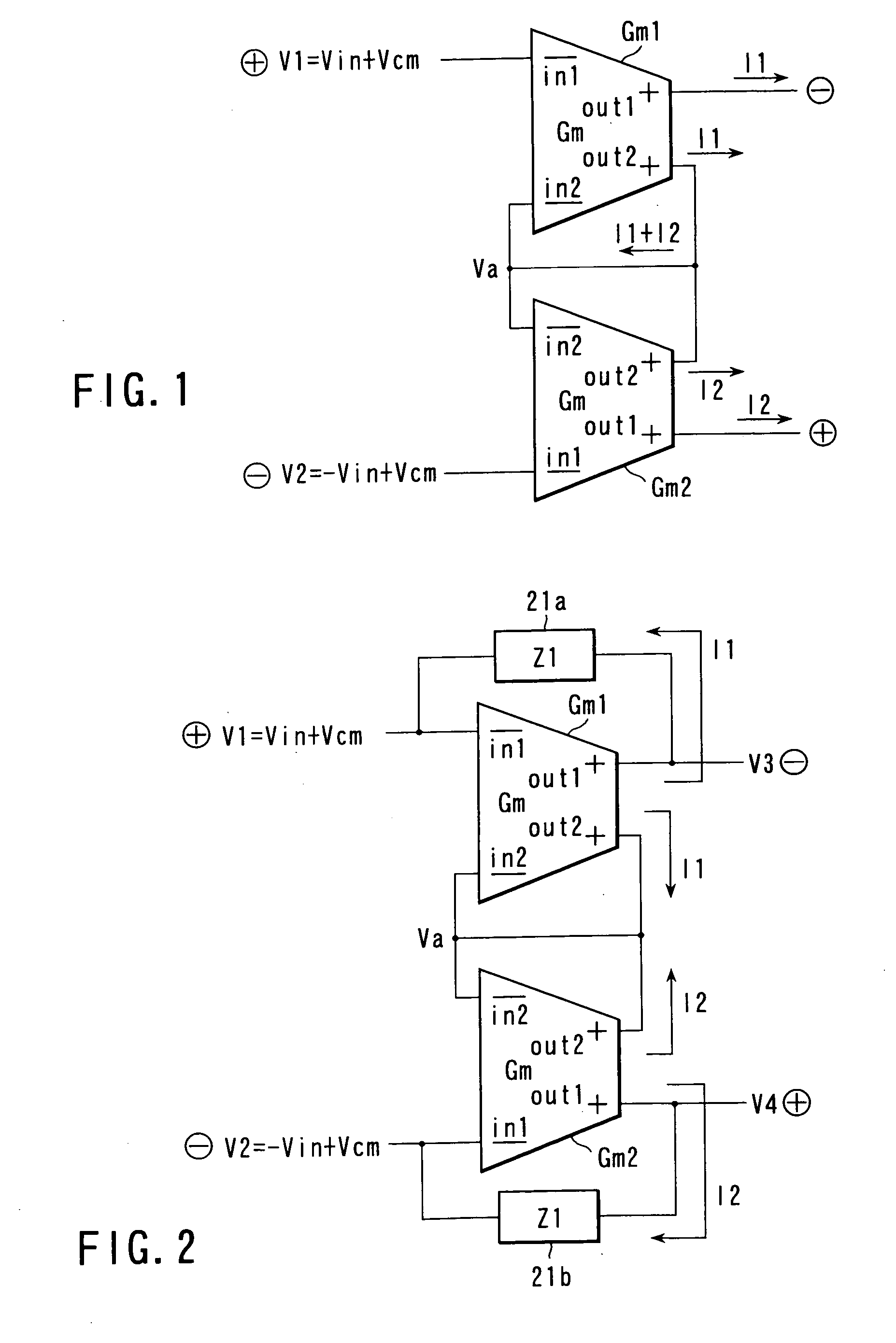
[0027] According to the present invention shown in FIG. 1, a balanced amplifier comprises voltage-to-current converters Gm1 and Gm2 each having four terminals, namely negative phase input terminals in1 and in2 and positive phase output terminals out1 and out2. The positive phase output terminal out2 and negative phase input terminal in2 of the voltage-to-current converter Gm1, and the positive phase output terminal out2 and negative phase input terminal in2 of the voltage-to-current converter Gm2 are commonly connected. Differential input signals are input from the negative phase input terminal in1 of the voltage-to-current converter Gm1 and the negative phase input terminal in1 of the voltage-to-current converter Gm2. Differential output signals are output from both the positive phase output terminal out1 of the voltage-to-current converter Gm1 and the positive phase output terminal out1 of the voltage-to-current converter Gm2.

[0028] The operations of the voltage-to-current convert...

second embodiment

[0059] FIG. 2 is a block diagram showing a balanced amplifier according to the second embodiment of the present invention. This balanced amplifier is a voltage-input / voltage-output balanced amplifier comprised of voltage-to-current converters Gm1 and Gm2 each having four terminals, namely negative phase input terminals in1 and in2 and positive phase output terminals out1 and out2, an impedance element 21a connected in parallel between the negative phase input terminal in1 and positive phase output terminal out1 of the voltage-to-current converter Gm1, and an impedance element 21b connected in parallel between the negative phase input terminal in1 and positive phase output terminal out1 of the voltage-to-current converter Gm2. The four terminals, i.e., negative phase input terminals in2 and positive phase output terminals out2 of the voltage-to-current converters Gm1 and Gm2 are connected to each other.

[0060] The operation of the balanced amplifier according to this embodiment will b...

third embodiment

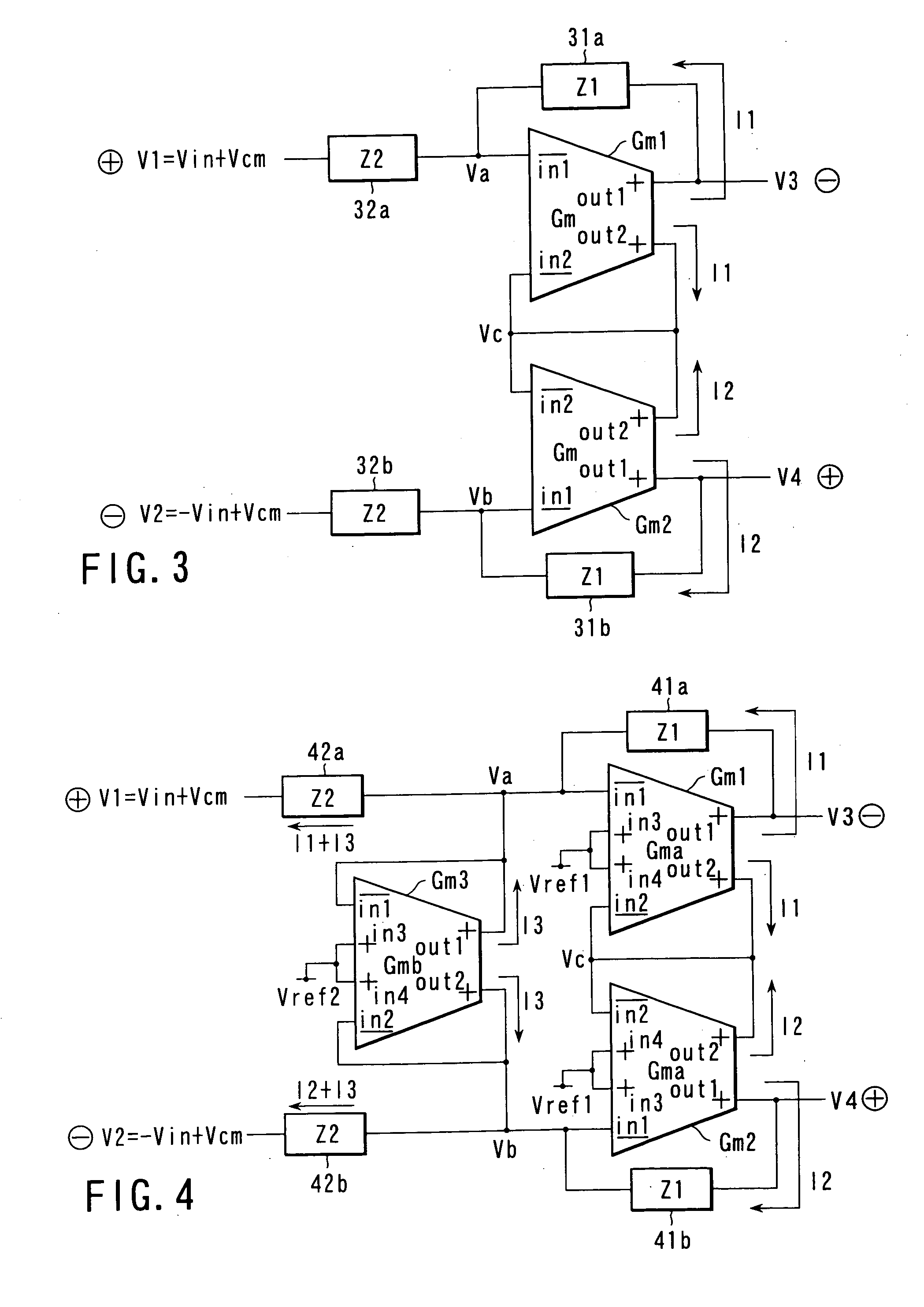
[0067] FIG. 3 is a block diagram showing a balanced amplifier according to the third embodiment of the present invention. This balanced amplifier is a voltage-input / voltage-output balanced amplifier comprised of voltage-to-current converters Gm1 and Gm2 each having four terminals, namely negative phase input terminals in1 and in2 and positive phase output terminals out1 and out2, an impedance element 31a connected in parallel between the negative phase input terminal in1 and positive phase output terminal out1 of the voltage-to-current converter Gm1, an impedance element 31b connected in parallel between the negative phase input terminal in1 and positive phase output terminal out1 of the voltage-to-current converter Gm2, an impedance element 32a having one terminal connected to the negative phase input terminal in1 of the voltage-to-current converter Gm1, and an impedance element 32b having one terminal connected to the negative phase input terminal in1 of the voltage-to-current con...


PUM


Abstract

A balanced amplifier comprising a pair of voltage-to-current converters including a first input terminal, a second input terminal, a first output terminal and a second output terminal to convert an input voltage applied to the first input terminal into an output current output from each of the first output terminal and the second output terminal, the second input terminal and the second output terminal of one of the converters being connected to the second input terminal and the second output terminal of the other of the converters to cancel common-mode components each other and extract differential-mode components.

Description

[0001] This application is based upon and claims the benefit of priority from the prior Japanese Patent Applications No. 2001-331805, filed Oct. 30, 2001; and No. 2002-090388, filed Mar. 28, 2002, the entire contents of both of which are incorporated herein by reference.[0002] 1. Field of the Invention[0003] The present invention relates to a balanced amplifier and a filter using the same and, more particularly, to a balanced amplifier whose maximum value of an output signal amplitude is larger than that of a conventional amplifier even at a low voltage, and a filter using the same.[0004] 2. Description of the Related Art[0005] A balanced amplifier has a gain only for the differential-mode components of an input signal and removes common-mode components. This balanced amplifier can remove noise mixed as common-mode components and double the amplitude of a differential signal as compared with the amplitude of a single-ended signal. Owing to such advantages, the balanced amplifier is ...

Claims


Application Information

Patent Timeline
Patent Type & Authority Applications(United States)
IPC IPC(8): H03F3/45H03H11/04
CPCH03F3/211H03F3/45475H03F3/45632H03F3/45766H03H11/32H03F3/45991H03F2203/45138H03H11/1247H03H11/0422H03F3/45928H03H11/045
Inventor UENO, TAKESHIITAKURA, TETSUROCZARNUL, KRYSTYMACZARNUL, ZDZISLAW
Owner KK TOSHIBA
Why Eureka
Try Eureka