Prosthetic foot with tunable performance

a technology of tunable feet and prosthetic feet, applied in the field of prosthetic feet with tunable feet, can solve the problems of limited dynamic response characteristics of this known artificial foot, and achieve the effects of improving applied mechanics, high performance, and high performan

Inactive Publication Date: 2004-09-23
BIOQUEST PROSTHETICS
View PDF93 Cites 12 Cited by
  • Summary
  • Abstract
  • Description
  • Claims
  • Application Information

AI Technical Summary

Benefits of technology

[0005] In order to allow the amputee athlete to attain a higher level of performance, there is a need for a high performance prosthetic foot having improved applied mechanics, which foot can out perform the human foot and also out perform the prior art prosthetic feet. It is of interest to the amputee athlete to have a high performance prosthetic foot having improved applied mechanics, high low dynamic response, and alignment adjustability that can be fine tuned to improve the horizontal and vertical components of activities which can be task specific in nature.

Problems solved by technology

However, the dynamic response characteristics of this known artificial foot are limited.

Method used


Image

  • Prosthetic foot with tunable performance
  • Prosthetic foot with tunable performance
  • Prosthetic foot with tunable performance

Examples


Embodiment Construction

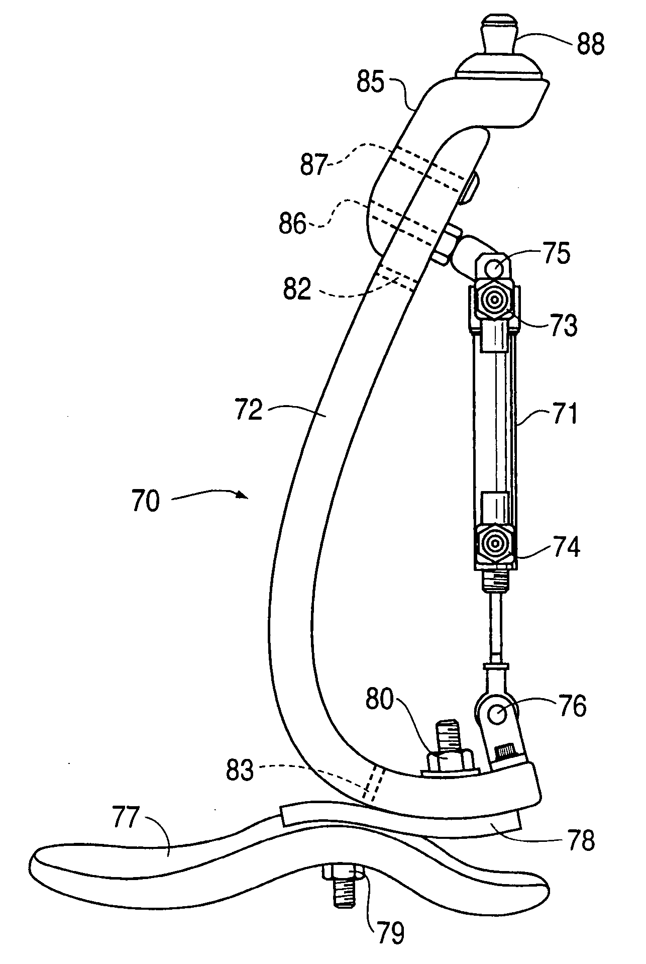
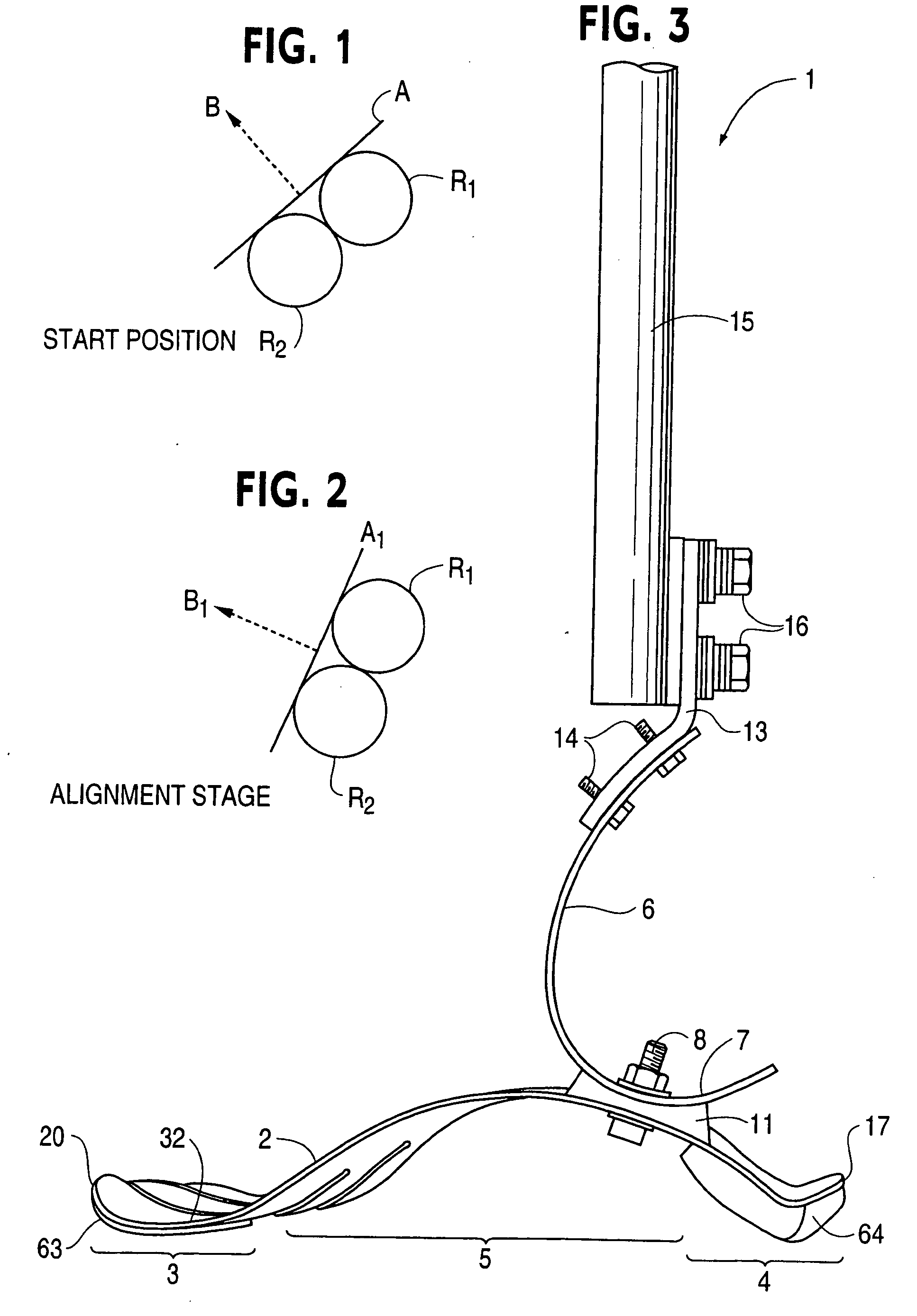
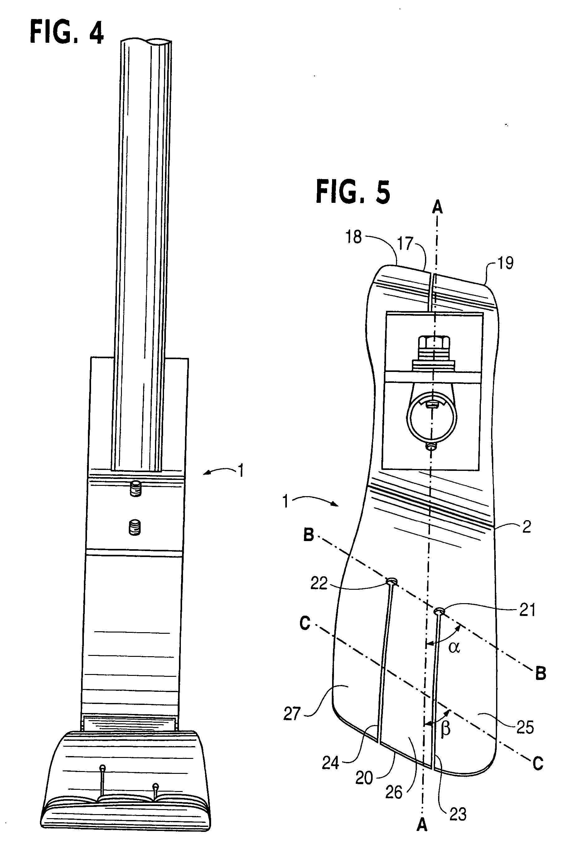
[0064] Referring now to the drawings, a prosthetic foot 1 in the example embodiment of FIGS. 3-5 is seen to comprise a longitudinally extending foot keel 2 having a forefoot portion 3 at one end, a hindfoot portion 4 at an opposite end and an upwardly arched midfoot portion 5 extending between the forefoot and hindfoot portions. The midfoot portion 5 is upward convexly curved over its entire longitudinal extent between the forefoot and hindfoot portions in the example embodiment.

[0065] An upstanding calf shank 6 of the foot 1 is attached at a portion of a downward convexly curved lower end 7 thereof to a proximate, posterior surface of the keel midfoot portion 5 by way of a releasable fastener 8 and coupling element 11. The fastener 8 is a single bolt with nut and washers in the example embodiment, but could be a releasable clamp or other fastener for securely positioning and retaining the calf shank on the foot keel when the fastener is tightened.

[0066] A longitudinally extending o...


PUM


Abstract

A prosthetic foot (124) incorporates a foot keel (165) and a calf shank (126) connected to the foot keel to form an ankle joint area of the prosthetic foot. The foot keel has forefoot and hindfoot portions and an upwardly arched midfoot portion extending between the forefoot and midfoot portions. The calf shank includes an anterior facing convexly curved lower portion which is adjustably attached at a portion thereof to the foot keel by way of a releasable fastener arrangement. The upper end of the calf shank is movable longitudinally of the foot keel in response to force loading and unloading the calf shank during use of the prosthetic foot. A device (125) connected between the upper end of the calf shank and the lower portion of the prosthesis can be used to assist posterior movement of the upper end of the calf shank and control anterior movement of the upper end of the calf shank during use of the prosthesis. The device (125) has springs which store energy during force loading with anterior motion of the upper end of the calf shank in gait and which, during force unloading, return the stored energy as kinetic power for adding to the propulsive force on the user's body generated by the prosthesis in gait.

Description

[0001] This application is a continuation in part of application Ser. No. 10 / 473,682, which is the U.S. national designated filing under 35 U.S.C. .sctn.371 of international application PCT / US02 / 09589 filed Mar. 29, 2002, which is a continuation in part of U.S. application Ser. No. 09 / 820,895, filed Mar. 30, 2001 and now U.S. Pat. No. 6,562,075 issued May 13, 2003, the priority of which is claimed. This application is also a continuation in part of application Ser. No. 10 / 263,795 filed Oct. 4, 2002, which is a continuation of U.S. application Ser. No. 09 / 820,895, filed Mar. 30, 2001 and now U.S. Pat. No. 6,562,075 issued May 13, 2003, the priority of which is claimed.[0002] The present invention relates to a high performance prosthetic foot providing improved dynamic response capabilities as these capabilities relate to applied force mechanics.[0003] A jointless artificial foot for a leg prosthesis is disclosed by Martin et al. in U.S. Pat. No. 5,897,594. Unlike earlier solutions wh...

Claims


Application Information

Patent Timeline
Patent Type & Authority Applications(United States)
IPC IPC(8): A61F2/00A61F2/50A61F2/60A61F2/66A61F2/70A61F2/74A61F2/76
CPCA61F2/60A61F2220/0075A61F2/6607A61F2/76A61F2002/30359A61F2002/30433A61F2002/30434A61F2002/30438A61F2002/30464A61F2002/30466A61F2002/5003A61F2002/5006A61F2002/5007A61F2002/5009A61F2002/5023A61F2002/503A61F2002/5032A61F2002/5033A61F2002/5075A61F2002/5079A61F2002/5083A61F2002/607A61F2002/6614A61F2002/6621A61F2002/6635A61F2002/6642A61F2002/665A61F2002/6657A61F2002/6664A61F2002/6671A61F2002/6678A61F2002/6685A61F2002/704A61F2002/745A61F2002/747A61F2002/7615A61F2220/0033A61F2220/0041A61F2/66A61F2002/30462A61F2/74
Inventor TOWNSEND, BARRY W.CLAUDINO, BYRON K.
Owner BIOQUEST PROSTHETICS
Why Eureka
Try Eureka