High flow stone basket system

a basket system and high-flow technology, applied in the field of medical devices, can solve the problems of poor fluid flow and visualization

Inactive Publication Date: 2004-10-07
APPL MEDICAL RESOURCES CORP
View PDF7 Cites 29 Cited by
  • Summary
  • Abstract
  • Description
  • Claims
  • Application Information

AI Technical Summary

Problems solved by technology

Thus, fluid flow and visualization become poor when a scope has its working channel almost completely filled with the basket and the outer sleeve.

Method used


Image

  • High flow stone basket system
  • High flow stone basket system
  • High flow stone basket system

Examples


second embodiment

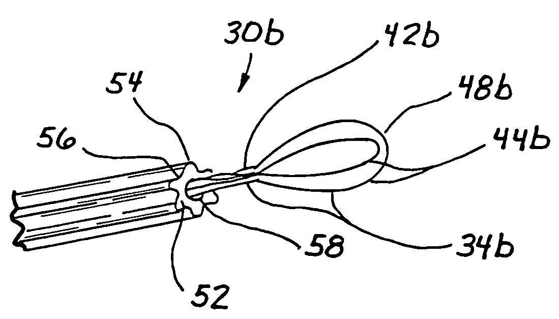
[0038] FIGS. 8-10 illustrate a sheathed basket device 30b according to the invention. Sheathed basket device 30b includes a basket sub-assembly 50 (see FIG. 10) that enables basket operation independent of endoscope 32b while optimizing fluid flow in endoscopic working channel 38b. Basket sub-assembly 50 comprises a ribbed basket sheath 52 having alternating configuration of axial ribs 54 and grooves / channels 56. Basket sheath 52 is inserted through a proximal end of endoscope 32b and is adapted to extend through the length of working channel 38b.

[0039] Basket sub-assembly 50 further includes a basket device 34b that is disposed in and through basket sheath 52. Similarly to basket device 34 in FIGS. 4-7, basket 34b comprises an elongate member 42b and a plurality of looped wires 44b forming a basket 48b. Basket 48b is deactivated by pulling elongate member 42b in a proximal direction causing looped wires 44b to collapse within a lumen 58 of basket sheath 52. With basket 48b collapse...

third embodiment

[0041] FIG. 11 illustrates a basket sub-assembly 50c according to the invention. Basket sub-assembly 50c comprises a basket actuator 64 and a basket device 34c. Basket device 34c comprises an elongate member 42c coupled to a plurality of looped wires 44c, which form a basket 48c. Basket actuator 64 comprises a thin control rod 66, which extends through the endoscopic working channel of the basket system (not shown), and a closure collar 68 coupling to a distal end of control rod 66. Basket actuator 64 is adapted to releasably retain basket 48c.

[0042] To deactivate basket 48c, elongate member 42c is pulled in a proximal direction to cause looped wires 44c to collapse within closure collar 68. With basket 48c collapsed and enclosed within closure collar 68, basket device 34c is secured to basket actuator 64 and basket sub-assembly 50c may be moved as one structure with respect to the endoscope. Therefore, basket sub-assembly 50c may be moved distally beyond the endoscope tip for an ex...

fourth embodiment

[0044] FIGS. 12 and 13 illustrate a basket system 30c according to the invention. Basket system 30c includes a basket sub-assembly 50d, which includes a basket device 34d, a tapered elongate member 42d and a tapered basket sheath 52d. Elongate member 42d comprises a distal portion 70 that increases in diameter as it extends distally so as to provide a distal end 72 with an expanded cross-sectional area for coupling a plurality of looped wires 44d, which form a basket 48d. The increased cross-sectional area of distal end 72 facilitates a stronger bond with looped wires 44d as more surface area is provided for coupling. To accommodate tapered elongate member 42d without limiting fluid flow, tapered basket sheath 52d is provided. Similarly to elongate member 42d, basket sheath 52d comprises a distal portion 74 that increases in diameter as it extends distally. That is, sheath distal portion 74 corresponds and conforms to the outer surface of distal portion 70 of elongate member 42d. Th...


PUM


Abstract

A medical device for viewing inside a body and for retrieving an object from a location within the body, the medical device comprising an endoscope having a tube defining a working channel and a basket engageable with the object. In one embodiment of the invention, the basket does not require a sheath and is disposed through the working channel such that the endoscope operates to contain or activate the sheathless basket. In another embodiment of the invention, a single push wire with a collar at its end is used in place of a sheath to control the opening and closing of the basket. In another embodiment of the invention, a tapered and funnel-shaped sheath surrounding the basket is used to contain or activate the basket. The invention minimizes the basket crossing profile so as to improve fluid flow in the working channel.

Description

[0001] This application claims benefit to U.S. Provisional Application Serial No. 60 / 329,241, filed Oct. 12, 2001, entitled "High-Flow Stone Basket System" as well as PCT Application Serial No. PCT / US02 / 18975 filed Jun. 14, 2002, entitled "High-Flow Stone Basket System", both of which are incorporated herein by reference.[0002] 1. Field of the Invention[0003] The present invention generally relates to medical devices and, more particularly, to a medical device for endoscopic retrieval of an object such as a stone from the body.[0004] 2. Description of Related Art[0005] Endoscopic urological procedures treat pathologies in the urinary system in a minimally invasive way by taking advantage of naturally existing body passages. These passages, such as the urethra and the ureter, allow a surgeon to reach deep inside the body with specially constructed instrumentation and tools. Endoscopic instrumentation and tools are manipulated from outside the body and can perform various functions in...

Claims


Application Information

Patent Timeline
Patent Type & Authority Applications(United States)
IPC IPC(8): A61B17/221A61B1/00A61B1/018A61B17/22A61MA61M1/00
CPCA61B1/018A61B17/221A61B2017/22072A61B2017/2212
Inventor CLAYMAN, RALPH VHILAL, NABILPINGLETON, EDWARD DEWERS, RICHARD C
Owner APPL MEDICAL RESOURCES CORP
Why Eureka
Try Eureka