Data multiplexing apparatus, data multiplexing method, and transmission apparatus

a data multiplexing and transmission apparatus technology, applied in the field of data multiplexing, can solve the problems of dynamic ram, small storage capacity, jitter of clocks that need to be absorbed for synchronization, etc., and achieve the effect of restricting the delay of the second packet stream

Active Publication Date: 2004-10-28
PANASONIC CORP
View PDF8 Cites 29 Cited by
  • Summary
  • Abstract
  • Description
  • Claims
  • Application Information

AI Technical Summary

Benefits of technology

The data multiplexing device and method can prevent delays for certain packets without affecting others. This helps improve overall efficiency and performance.

Problems solved by technology

The technical problem addressed in this patent is reducing delays in transmitting multiplexed packet streams through a data multiplexing apparatus without compromizing privacy and performance requirements. Previous methods have resulted in long delays due to issues with latency in processing and multiplexing packet buffers, leading to impact users' experience and slow downstream distribution rates. This new approach provides a solution by introducing a data multiplexing apparatus capable of efficiently removing null pointers and replacing them with private data packets.

Method used


Image

  • Data multiplexing apparatus, data multiplexing method, and transmission apparatus
  • Data multiplexing apparatus, data multiplexing method, and transmission apparatus
  • Data multiplexing apparatus, data multiplexing method, and transmission apparatus

Examples


first embodiment

[0094] (First Embodiment)

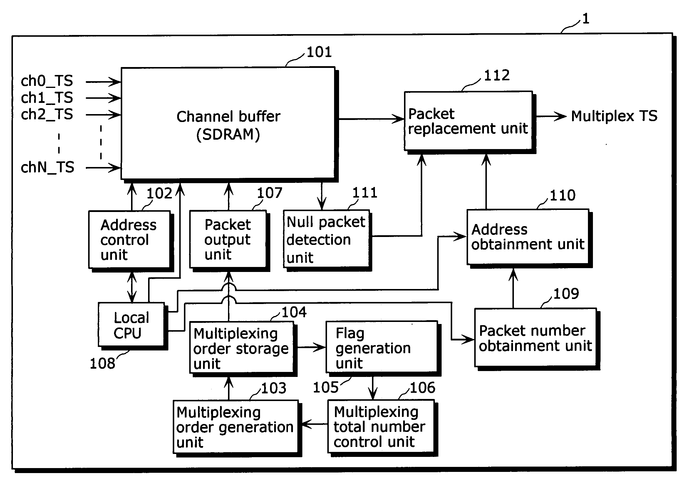
[0095] FIG. 8 is a block diagram showing a structure of a data multiplexing apparatus 1 according to the first embodiment of the present invention.

[0096] The data multiplexing apparatus 1 in the present embodiment receives MPEG2-TSs (packet streams) of multiple channels and outputs a single multiplexed MPEG2-TS. As shown in FIG. 8, the data multiplexing apparatus 1 includes a channel buffer 101, an address control unit 102, a multiplexing order generation unit 103, a multiplexing order storage unit 104, a flag generation unit 105, a multiplexing total number control unit 106, a packet output unit 107, a local CPU 108, a packet number obtainment unit 109, an address obtainment unit 110, a null packet detection unit 111 and a packet replacement unit 112.

[0097] In the present embodiment, the channel buffer 101 is a packet stream storage unit described in the claims. Therefore, it does not mean that the packet stream storage unit of the present invention is limi...

second embodiment

[0167] (Second Embodiment)

[0168] FIG. 13 is a block diagram showing the structure of the transmission and reception system according to the second embodiment of the present invention. This transmission and reception system includes a server apparatus 501, a transmission apparatus 502 and a reception apparatus 503.

[0169] The server apparatus 501 stores multi-channel contents to be transmitted, and supplies the transmission apparatus 502 with the contents.

[0170] The transmission apparatus 502 has the data multiplexing apparatus 1 and a transmission unit 5021. The data multiplexing apparatus 1 obtains a content (a packet stream) per channel from the server apparatus 501. Since the data multiplexing apparatus 1 has been explained in detail in the first embodiment, the explanation thereof is not repeated here.

[0171] The transmission unit 5021 transmits a multiplexed stream outputted from the data multiplexing apparatus 1. It is preferable to realize the transmission unit 5021 by broadcas...


PUM


Abstract

A data multiplexing apparatus (1) includes: a packet number obtainment unit (109) for obtaining the total number of packets included in one block on a private data packet stream inputted into a channel buffer (101); an address obtainment unit (110) for obtaining the address of the starting packet in each private data block; a null packet detection unit (111) for detecting null packets when a multiplexed packet stream of data other than the private data is outputted from the channel buffer (101); and a packet replacement unit (112) for replacing the multiplexed null packets detected by the null packet detection unit (111) with the private data packets and outputting the multiplexed packet stream.

Description


Claims


Application Information

Patent Timeline
Owner PANASONIC CORP
Why Eureka
Try Eureka