
Method and data processing system for microprocessor communication in a cluster-based multi-processor network

a multi-processor network and microprocessor technology, applied in the field of data processing, can solve the problems of large interconnect bandwidth consumption, high communication latency, and large coherency

Inactive Publication Date: 2004-10-28
IBM CORP
View PDF3 Cites 6 Cited by
  • Summary
  • Abstract
  • Description
  • Claims
  • Application Information

AI Technical Summary

Benefits of technology

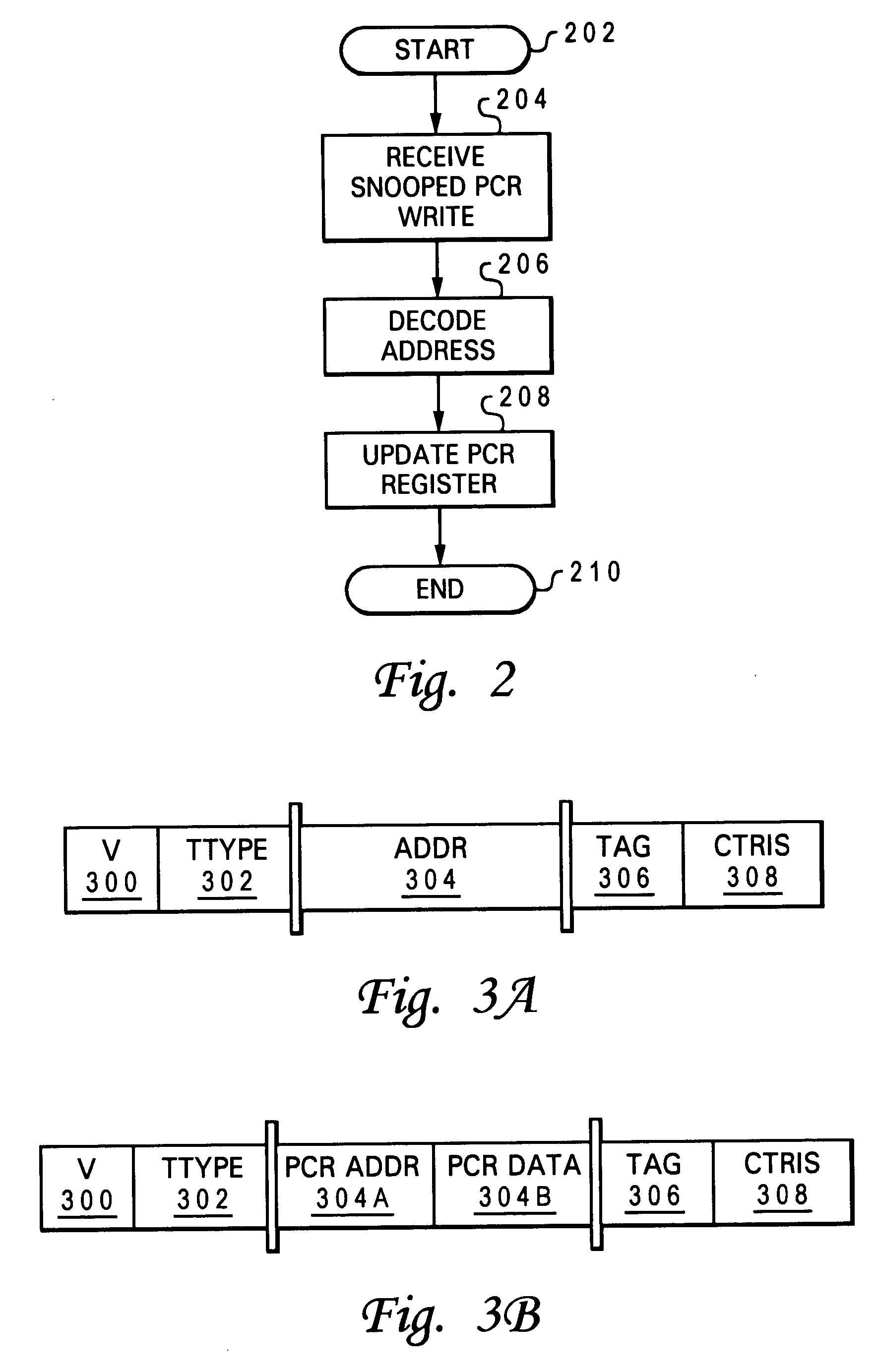
[0023] Disclosed is a method, processor and multi-processor (MP) system for enabling fast and efficient updates of synchronization data stored within processor communication registers (PCRs) of individual processors of a multi-processor data processing system. A modified address tenure is provided that includes an indication that the address tenure is a PCR-targeted address tenure as well as the synchronization data being updated within the individual PCRs. The modified address tenure is broadcast on the address bus and snooped by each processor concurrently.

Problems solved by technology

Furthermore, in circumstances of high contention in modem cache based multiprocessors, these shared memory lock techniques can lead to a great deal of coherency and data traffic on system interconnection buses to manage the lock variables.
The transactions related to lock variables consume large amounts of interconnect bandwidth and incur high communication latency relative to the small percentage and size of information transmitted through the lock variables.
However, another processing element may not be able to allow the operation to proceed and would produce a "retry" snoop response.
Unlike the address bus portion of the system interconnect, the data bus portion of the system interconnect is typically not designed to broadcast the transferred data to all participants within the multiprocessor system.
Due to the multi-beat nature of data transfers and the bandwidth required, it is impractical and unnecessary to make any given data transfer visible to all processor chips within the system.
When a lock is released due to a store, these cached copies will be invalidated causing the participating processors to attempt to re-acquire the lock.
The leads to long interconnect latencies and significant use of interconnect bandwidth and resources.

Method used


Image

  • Method and data processing system for microprocessor communication in a cluster-based multi-processor network
  • Method and data processing system for microprocessor communication in a cluster-based multi-processor network
  • Method and data processing system for microprocessor communication in a cluster-based multi-processor network

Examples


Embodiment Construction

)

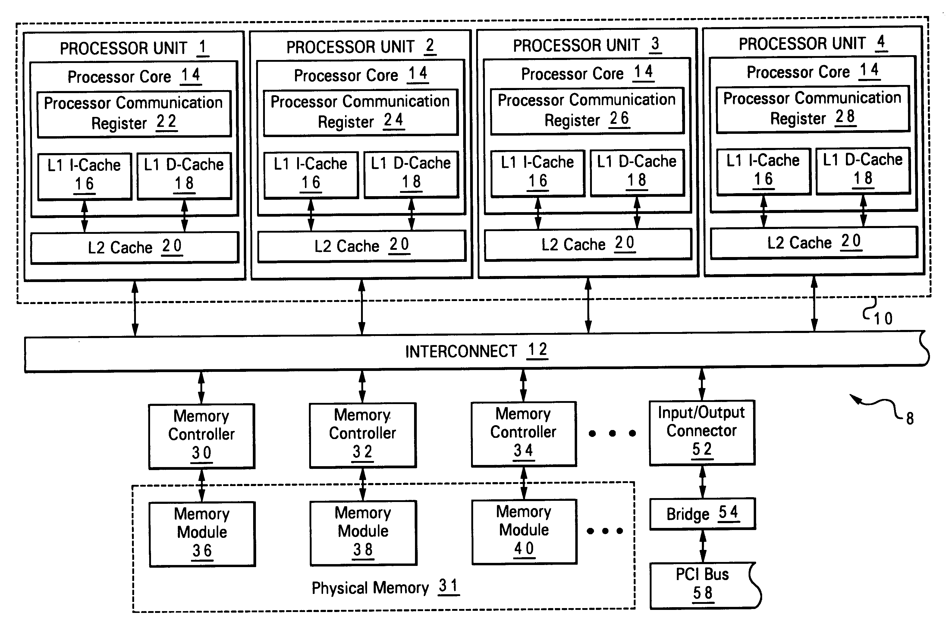
[0033] The present invention is implemented, among other places, within the multi-processor (MP) configuration described in the related applications in which each processor in the MP is designed with a processor communication register (PCR). The relevant content of the related applications are incorporated herein by reference. As noted within these related applications, it is often the case where there are a small number of critical synchronization variables that are shared by a large number of the processors (for example, for a hypervisor). For these cases, special registers that are duplicated within every chip are provided and referred to as PCRs. With these PCRs, each chip accomplishes read operations to it's own local copy of the register and a processor which writes to the register updates all the copies of the registers within all processor chips.

[0034] To efficiently support these duplicated registers, a means needs to be provided to allow for the registers to be efficientl...


PUM


Abstract

The address tenure for PCR synchronization operations is redefined to support inclusion of the synchronization data within the address tenure. The bits of a particular field within the address tenure (e.g., the address field) are re-allocated to synchronization data, which is known to be small enough to fit within the unused bits. The address tenure is then broadcasted as a normal address operation and is snooped by all of the processors. The snooping logic is designed to recognize regular / normal address tenures and these modified address tenures and respond to a receipt of a modified address tenure by removing the synchronization data stored therein and updating the corresponding register location of the PCR.

Description

[0001] The present invention is related to the subject matter of the following commonly assigned, copending United States patent applications: (1) Ser. No. 10 / 308,514 (Docket No. AUS920020180US1) entitled "Method, Processing Unit and Data Processing System for Microprocessor Communication in a Multi-Processor System" and filed Dec. 12, 2002; (2) Ser. No. 10 / 318,515 (Docket No. AUS920020181US1) entitled "Method and Data Processing System for Microprocessor Communication Using a Processor Interconnect in a Multi-Processor System" and filed Dec. 12, 2002; and (3) Ser. No. 10 / 313,516 (Docket No. AUS920020182US1) entitled "Method and Data Processing System for Microprocessor Communication in a Cluster-Based Multi-Processor System" and filed Dec. 12, 2002. The content of the above-referenced applications is incorporated herein by reference.PRIORITY DATE[0002] The present invention hereby claims the priority filing date of Dec. 12, 2002 of the above referenced related applications.[0003] 1...

Claims


Application Information

Patent Timeline
Patent Type & Authority Applications(United States)
IPC IPC(8): G06F9/46G06F12/08
CPCG06F9/52G06F12/0831
Inventor ARIMILLI, RAVI KUMARWILLIAMS, DEREK EDWARD
Owner IBM CORP
Learn More