
Hoist

a technology of a sled and a sled body, applied in the field of sleds, to achieve the effect of increasing the travel of the sled, and reducing the movement of the moving pivot link

Inactive Publication Date: 2004-11-25
HUNTLEIGH TECH LTD
View PDF7 Cites 5 Cited by
  • Summary
  • Abstract
  • Description
  • Claims
  • Application Information

AI Technical Summary

Benefits of technology

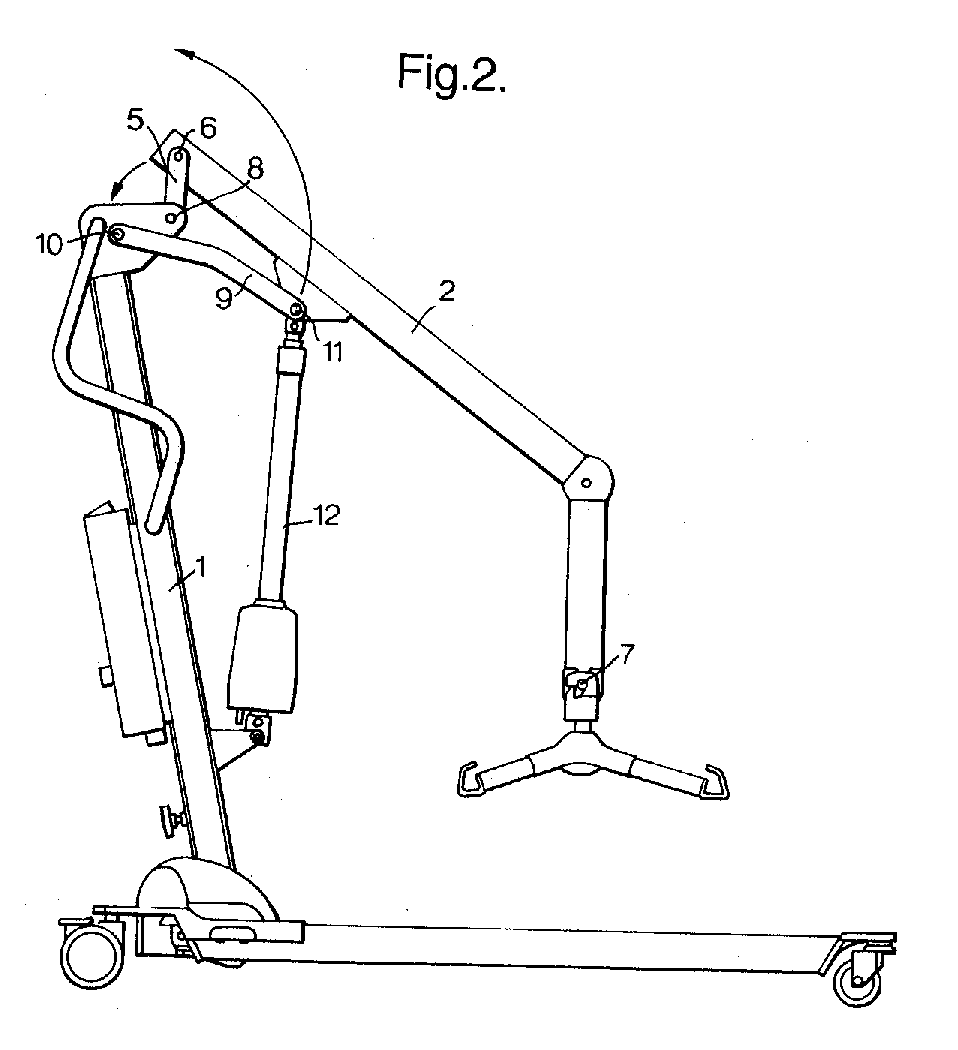
[0004] The present invention seeks to make improvements. Accordingly, the present invention provides a hoist comprising a chassis, a mast upstanding from the chassis, the mast pivotally supporting a lifting arm at one end wherein the position of the pivot varies with movement of the lifting arm. Among other advantages, the provision of a moving pivot between the mast and the lifting arm results in a larger lifting range for a given lifting arm driven by an actuator of given length. The moving pivot may comprise a link pivotally connected to the mast about a fixed point and pivotally connected to the lifting arm about a moving pivot point. A stabilizing link attached to the mast and actuator may restricts the movement of the moving pivot link.
[0005] By the provision of a moving pivot, the invention increases the travel of the lift normally achieved by the same actuator in a fixed pivot hoist.
[0006] Thus a smaller, discreet and economic actuator can achieve a greater lifting range and reach.

Problems solved by technology

However, with such known hoists the lifting arm moves through a limited range of movement between the high and low positions and further requires a large actuator for its operation.

Method used


Image

  • Hoist
  • Hoist
  • Hoist

Examples


Embodiment Construction

Cross Reference to Related Applications

[0001] This application claims priority to United Kingdom patent application No. 0304176.1, filed February 24, 2003.

Background of Invention

[0002] The invention relates to a hoist.

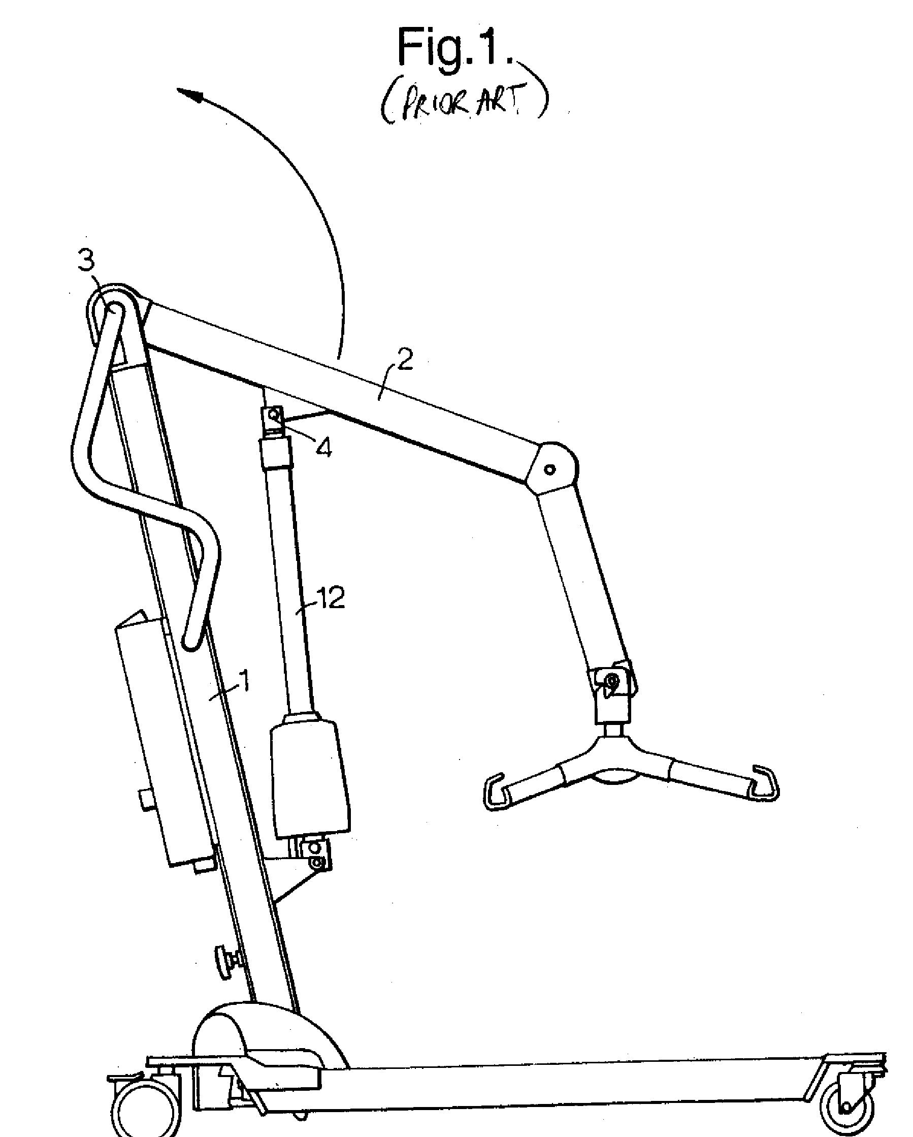
[0003] It is known to have hoists comprising a mobile chassis, a mast upstanding from the chassis pivotably supporting a lifting arm at its upper end, the lifting arm having a sling attachment at its opposite end. An actuator between the mast and the lifting arm moves the lifting arm about its pivot point with the mast through a given arc. Figure 1 shows such a prior art hoist with an actuator 12 connected to a mast 1 of the hoist and driving a lifting arm 2 by means of pivot 4, the lifting arm 2 rotated about an arc around pivot 3 on the upper part of the mast 1 of the hoist. However, with such known hoists the lifting arm moves through a limited range of movement between the high and low positions and further requires a large actuator for its operation.

Summary of Inv...


PUM


Abstract

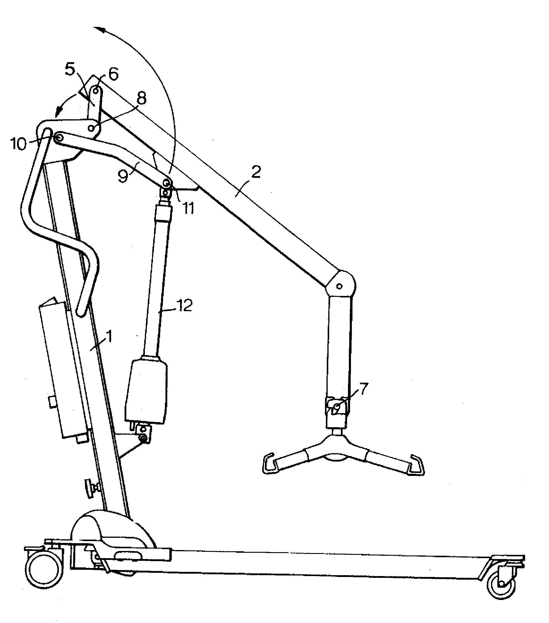
Abstract of the Disclosure A hoist pivotally connecting mast 1 to lifting arm 2, by a mechanism comprising a link 5 pivoting about a fixed pivot 8 on the mast 1 and a moving pivot 6 on the lifting arm 2. A restraining link 9 between a pivot 10 on the mast 1 and actuator attachment point 11 on the lifting arm 2 restricts the movement of link 5. The second link 9 acts as a stabilizer allowing the pivot 11 on the lifting arm 2 to move only through a set arc, determined by the length of the link 9 and the position of the pivot 10 on the mast 1. With the moving pivot according to the invention, the spreader bar attachment point 7 has a greater traveling distance than if it were simply pivoted about pivot 8 as with conventional hoists.

Description

Detailed Description of the InventionCross Reference to Related Applications[0001] This application claims priority to United Kingdom patent application No. 0304176.1, filed February 24, 2003.Background of Invention[0002] The invention relates to a hoist.[0003] It is known to have hoists comprising a mobile chassis, a mast upstanding from the chassis pivotably supporting a lifting arm at its upper end, the lifting arm having a sling attachment at its opposite end. An actuator between the mast and the lifting arm moves the lifting arm about its pivot point with the mast through a given arc. Figure 1 shows such a prior art hoist with an actuator 12 connected to a mast 1 of the hoist and driving a lifting arm 2 by means of pivot 4, the lifting arm 2 rotated about an arc around pivot 3 on the upper part of the mast 1 of the hoist. However, with such known hoists the lifting arm moves through a limited range of movement between the high and low positions and further requires a large actu...

Claims


Application Information

Patent Timeline
Patent Type & Authority Applications(United States)
IPC IPC(8): A61G7/10B66C23/48
CPCA61G7/1011A61G7/1017A61G7/1046A61G7/1061B66C23/48
Inventor BROOKS, LES
Owner HUNTLEIGH TECH LTD
Learn More