
Horizontal cramp machine for laminating motor stator iron cores

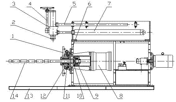
A motor stator and horizontal technology, which is applied in the field of special mechanical equipment for lamination of motor stator iron core, can solve the problem of small diameter range of motor stator iron core, poor lamination uniformity of vertical lamination machine, stator core rotation Difficulties and other problems, to achieve the effect of reduced investment, neat lamination, and convenient movement

Inactive Publication Date: 2012-07-04
襄阳中车电机技术有限公司
View PDF0 Cites 3 Cited by
  • Summary
  • Abstract
  • Description
  • Claims
  • Application Information

AI Technical Summary

Problems solved by technology

[0002] At present, the motor stator iron core lamination and buckling machine known or used by the motor factory is mainly vertical, and its disadvantages are: ①The vertical lamination machine has poor lamination uniformity, complex equipment installation, and deep pits need to be dug It is inconvenient to make the foundation and move the equipment; ②The diameter range of the processed motor stator core is small, and it is difficult to rotate the stator core under the action of stacking pressure when buckling the film, and the operation is not easy

Method used


Image

  • Horizontal cramp machine for laminating motor stator iron cores
  • Horizontal cramp machine for laminating motor stator iron cores

Examples


Embodiment Construction

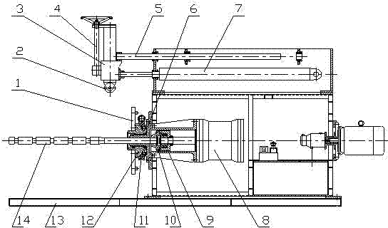
[0012] like figure 1 As shown, the main hydraulic cylinder 8 is horizontally fixed on the machine body through the supporting fixed sleeve 6, the auxiliary hydraulic cylinder 7 is horizontally fixed above the main hydraulic cylinder 8, and the piston rod of the main hydraulic cylinder 8 is connected with a piston rod tension transmission mechanism, and the tension The transmission mechanism is that two plane thrust bearings are installed on the piston rod of the main hydraulic cylinder 8, and the right tension sleeve 9 is installed on the bearing, and the right tension sleeve 9 is connected with the left tension sleeve 10 on the tension rod 14 through bolts, and at the same time, When the tension rod 14 rotates with the stator core of the motor, the piston rod of the main hydraulic cylinder 8 cannot rotate. There are at least five annular grooves on the tension rod 14; Connection; the supporting fixed sleeve 6 is connected with the supporting movable sleeve 12, and the support...


PUM


Abstract

The invention discloses a horizontal cramp machine for laminating motor stator iron cores, relates to a special cramp machine for laminating motor stator iron cores and particularly relates to a horizontal cramp machine for laminating motor stator iron cores with diameter and height of more than 300mm-1000mm. The horizontal cramp machine is mainly used for solving the problems that the lamination uniformity is poor, the diameter range of processed motor stator iron cores is small, the iron core is difficult to rotate when cramping is performed and the installation is complex in the existing cramp machine for motor stator iron cores. In horizontal cramp machine provided by the invention, a main hydraulic cylinder is horizontally fixed on a machine body, a secondary hydraulic cylinder is horizontally fixed above the main hydraulic cylinder, a piston rod of the main hydraulic cylinder is connected with a piston rod tension transmission mechanism, a laminating tyre connecting disc is connected to the main hydraulic cylinder through a support moving sleeve, a piston rod of the secondary hydraulic cylinder is provided with a pressure head lifting mechanism. The lifting range of a sleeve in the invention is large, the motor stator iron core rotates freely along with a fixture when being laminated and cramped, a tension rod rotates along with the motor stator iron core but the piston rods of the hydraulic cylinders do not rotate, and the installation of the machine is convenient.

Description

technical field [0001] The invention relates to a special mechanical device for lamination and buckling of motor stator cores, in particular to a horizontal buckling machine for lamination of motor stator cores with a diameter and height of 300mm-1000mm and above. Background technique [0002] At present, the motor stator iron core lamination and buckling machine known or used by the motor factory is mainly vertical, and its disadvantages are: ①The vertical lamination machine has poor lamination uniformity, complex equipment installation, and deep pits need to be dug It is inconvenient to make the foundation and move the equipment; ②The diameter range of the processed motor stator core is small, and it is difficult to rotate the stator core under the action of stacking pressure when buckling the film, and the operation is not easy. Contents of the invention [0003] The object of the present invention is to overcome the above-mentioned shortcomings, and provide a motor sta...

Claims


Application Information

Patent Timeline
Patent Type & Authority Applications(China)
IPC IPC(8): H02K15/02
Inventor 潘则名
Owner 襄阳中车电机技术有限公司
Learn More