Actuator

a technology of actuators and pistons, applied in the field of actuators, can solve the problems that the push rod may not project satisfactorily from the piston portion,

Inactive Publication Date: 2005-01-06
NHK SPRING CO LTD
View PDF4 Cites 19 Cited by
  • Summary
  • Abstract
  • Description
  • Claims
  • Application Information

AI Technical Summary

Problems solved by technology

However, the technique disclosed in Jpn. Pat. Appln. KOKAI Publication No. 2002-29369 has no arrangement which discharges the high-pressure gas from the cylinder unit.
I...

Method used


Image

  • Actuator
  • Actuator
  • Actuator

Examples


first embodiment

[0033] the present invention will be described with reference to FIGS. 1 and 2.

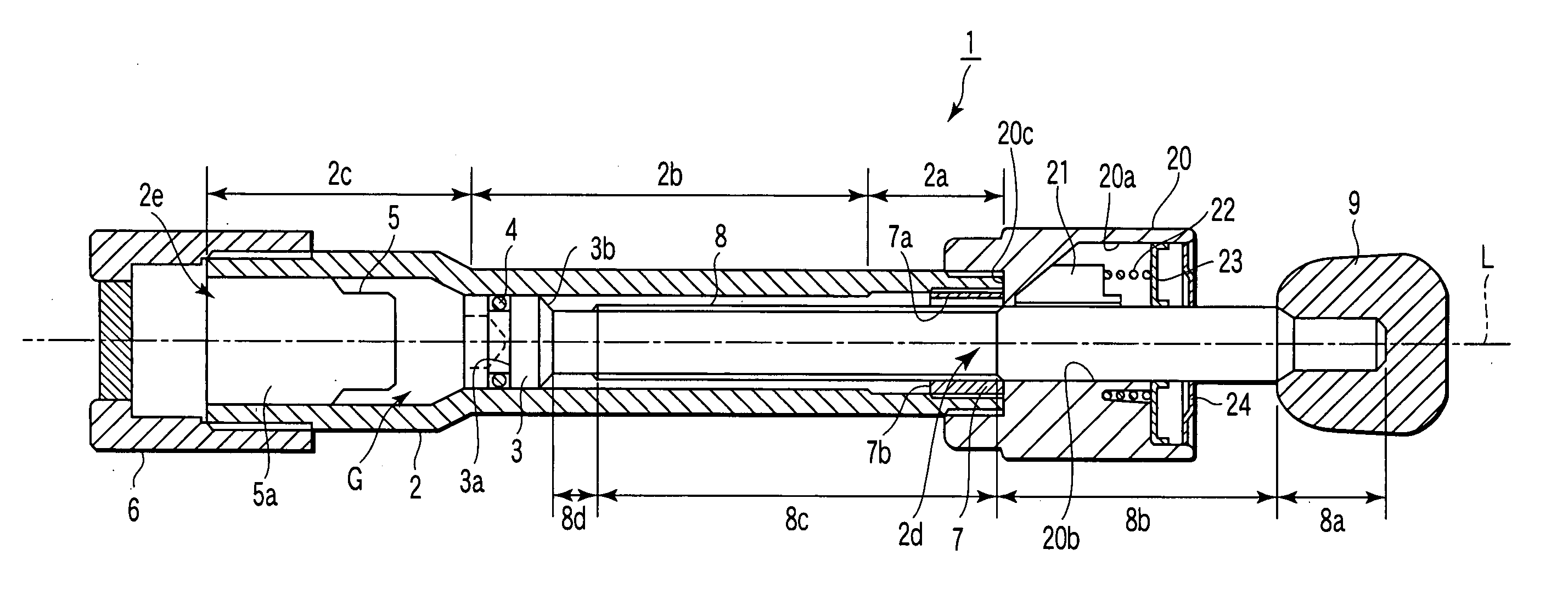
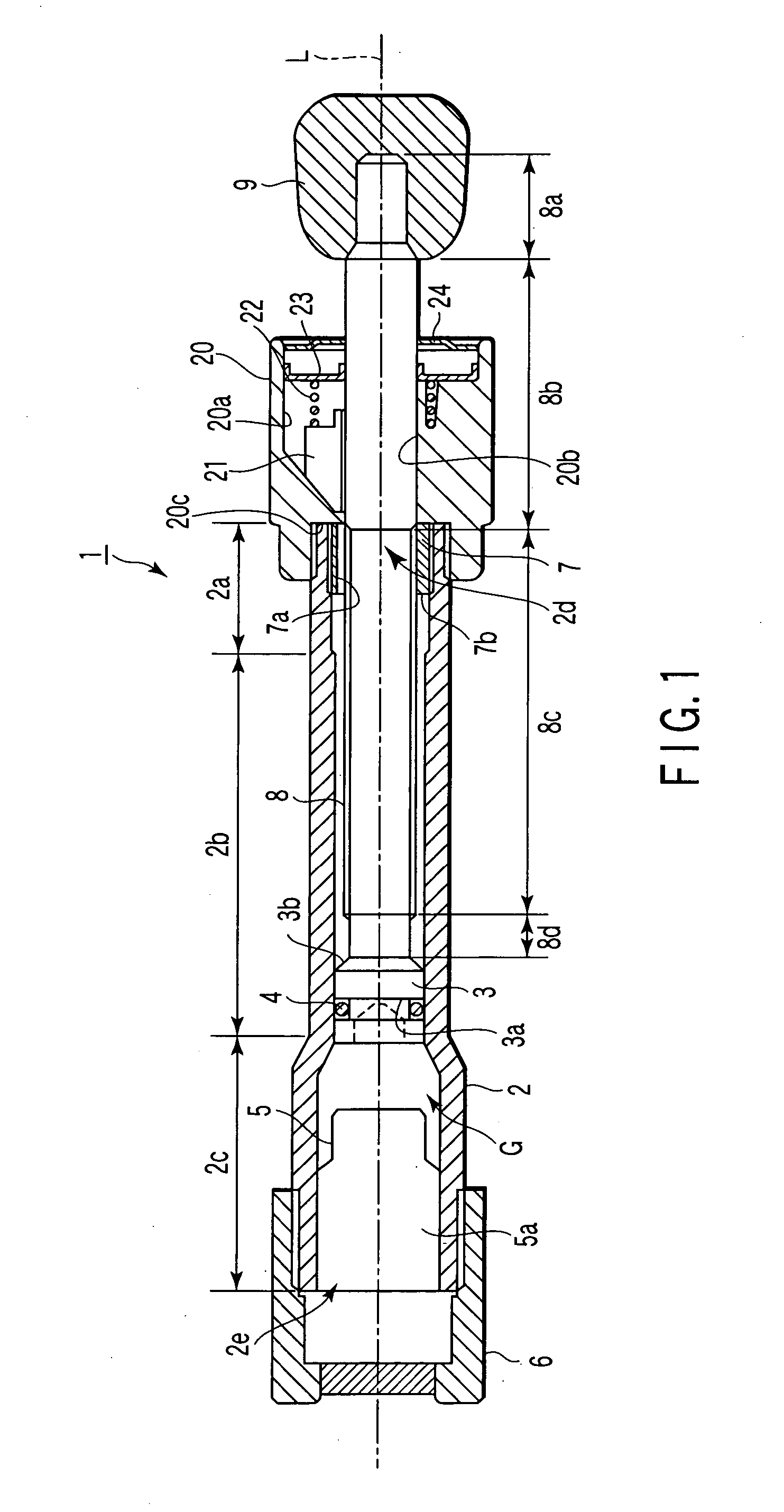
[0034] As shown in FIG. 1, the actuator 1 of this embodiment comprises the cylinder 2, a piston 3, an O-ring 4 serving as a sealing member, a gas generator 5, a cap 6, a stopper 7, the piston rod 8, and a piston head 9.

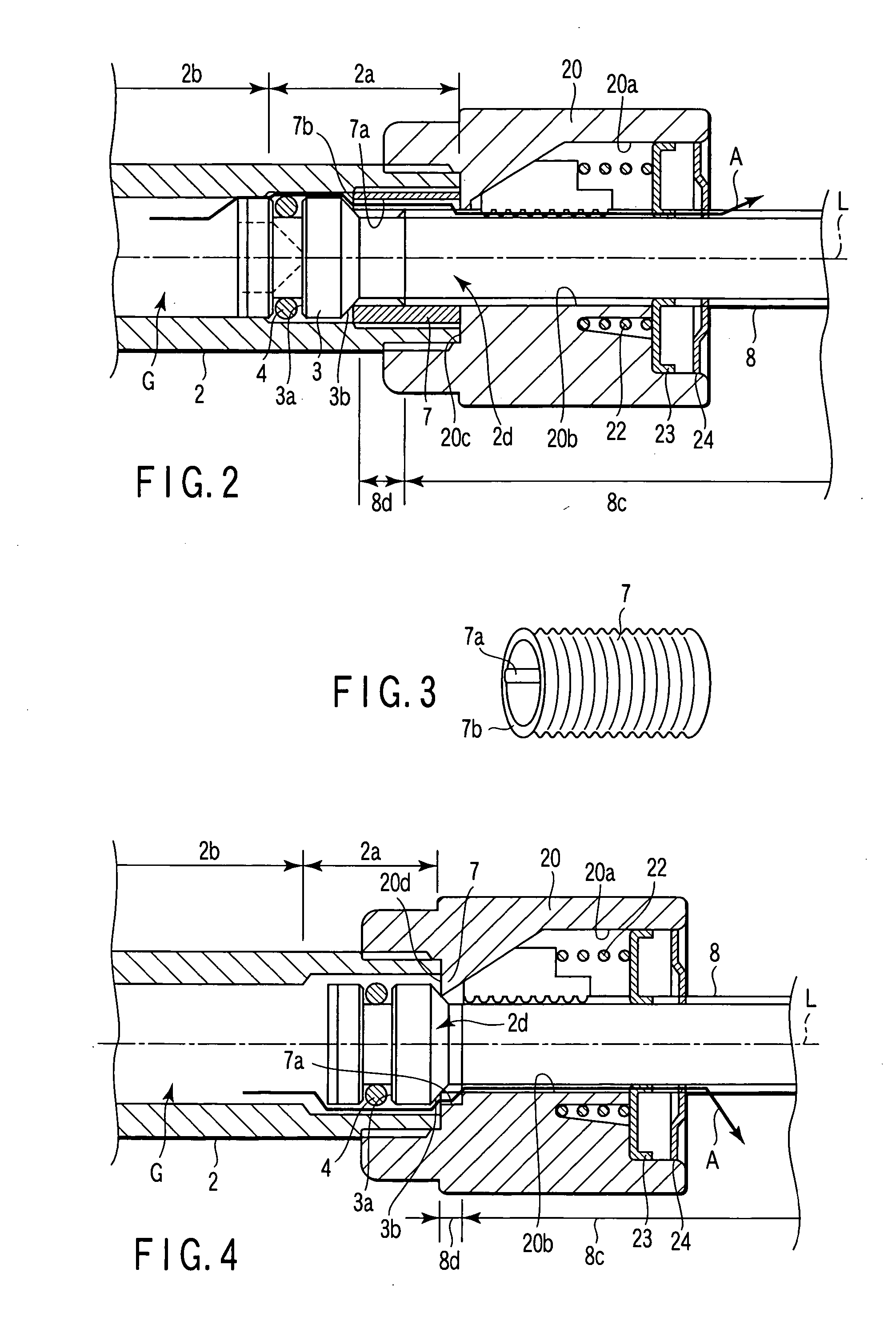
[0035] As shown in FIGS. 1 to 3, the hollow cylinder 2 has open ends 2d and 2e at the front and rear ends, respectively. The cylinder 2 has a front end portion 2a as the first part, an intermediate portion 2b as the second part, and a rear end portion 2c as the third part. The intermediate portion 2b is located between the front end portion 2a and the rear end portion 2c. The inner diameter of the front end portion 2a of the cylinder 2 is larger than that of the intermediate portion 2b. The outer and inner diameters of the rear end portion 2c of the cylinder 2 are larger than those of the intermediate portion 2b and front end portion 2a. The cylinder 2 has a cylinder head 20. The cylinder ...

second embodiment

[0056] the present invention will be described below with reference to FIG. 4.

[0057] In this embodiment, the cylinder 2 and a stopper 7 are integrated. In this case, the stopper 7 can be integrated with, e.g., a cylinder head 20 of the cylinder 2.

[0058] In this embodiment, a bottom portion 20d of a cylinder storage recess portion 20c of the cylinder head 20 serves as the butt surface to a piston 3. A vent groove 7a is formed in an inner surface which forms a through hole 20b of the cylinder head 20. The vent groove 7a makes a front end portion 2a of the cylinder 2 communicate with a storage unit 20a of the cylinder head 20. The remaining components including those not illustrated are the same as in the above-described first embodiment. The same reference numerals as in the first embodiment denote the same parts in the second embodiment, and a repetitive description thereof will be omitted.

[0059] In this embodiment, the same effect as in the first embodiment can be obtained. In thi...


PUM


Abstract

An actuator includes a hollow cylinder which has a first portion and a second portion. The inner diameter of the first portion is larger than that of the second portion. A piston is inserted in the cylinder. The actuator has a gas generator which supplies a gas into the cylinder to move the piston toward the first portion. The seal member keeps airtightness between the piston and the cylinder when the piston stays in the second portion and flows the gas when the piston stays in the first portion. A hollow stopper is arranged in the first portion and stops the piston. The stopper has a vent groove which is provided on the inner surface and connects the interior of the cylinder to the open end. A piston rod is jointed to the piston and housed in the cylinder. The piston rod moves along the axis with the piston.

Description

CROSS-REFERENCE TO RELATED APPLICATIONS [0001] This application is based upon and claims the benefit of priority from prior Japanese Patent Application No. 2003-190371, filed Jul. 2, 2003, the entire contents of which are incorporated herein by reference.BACKGROUND OF THE INVENTION [0002] 1. Field of the Invention [0003] The present invention relates to an actuator applied to, e.g., the hood apparatus of a car. [0004] 2. Description of the Related Art [0005] If a pedestrian were hit on the front of a running car, the lower half of his / her body may be stricken by the bumper at the nose of the car. In this case, he / she is thrown on the hood of the car and hit, e.g., the head against it. [0006] Under these circumstances, some cars have hood apparatuses. A hood apparatus is designed to operate an actuator to push the hood upward when a sensor arranged at the nose of the car detects a pressure with a predetermined value or more. When the hood is pushed up, a gap is formed between the hoo...

Claims


Application Information

Patent Timeline
IPC IPC(8): B60R21/02B62D25/10B60R21/34B60R21/38B60R22/46F15B15/19
CPCF15B15/19B60R21/38
Inventor YAMAGUCHI, HIROYOSHITAKAKURA, MINORU
Owner NHK SPRING CO LTD
Why Eureka
Try Eureka