Lace blocking device

a technology of lace and lace, which is applied in the direction of textile cables, ropes and cables for vehicles/pulleys, applications, etc., can solve the problems of difficult unblocking operation, difficult unblocking operation, and difficult unblocking operation, so as to achieve greater unblocking facility and easy grasping and manipulation

Inactive Publication Date: 2005-01-13
SALOMON SA
View PDF10 Cites 28 Cited by
  • Summary
  • Abstract
  • Description
  • Claims
  • Application Information

AI Technical Summary

Benefits of technology

[0018] To this end, the invention is directed to a blocking device, acting at least on one strand, having a rotational axis for a blocking member, also having a hollow body, one cavity of which defines at least one path for the passage of each strand, on the one hand, and a housing for the blocking member, on the other hand, the blocking member having a circular form and being free in rotation about the axis that is itself movable in translation, the device functioning by cooperation of the blocking member with each path for the blocking of each strand through a wedging effect, the blocking member being elastically biased in the direction for blocking the strand(s) by action on its rotational axis, the device further having a member for unblocking the blocking member.
[0020] The gripping portion constitutes an appendage that projects with respect to the hollow body. As a result, the gripping portion is easy to grasp and manipulate. Consequently, the unblocking force can be exerted without it being necessary to hold the hollow body. A resulting advantage is a greater facility for unblocking the device blocking member.

Problems solved by technology

It has been noted that the unblocking operation is not always easy.
The holding of the body in conjunction with the displacement of the pushing member can be a relatively difficult operation.
It is even more difficult when the size of the device is made to be relatively small.
Additionally, the device is often housed in an area that is hard to reach and is cramped.
Consequently, the accessibility to the device is reduced, which contributes to the difficulty in actuating the pushing member.
Finally, the unblocking is even more difficult when the user wears gloves, as the latter hinder the manipulation of the device.

Method used


Image

  • Lace blocking device
  • Lace blocking device
  • Lace blocking device

Examples


first embodiment

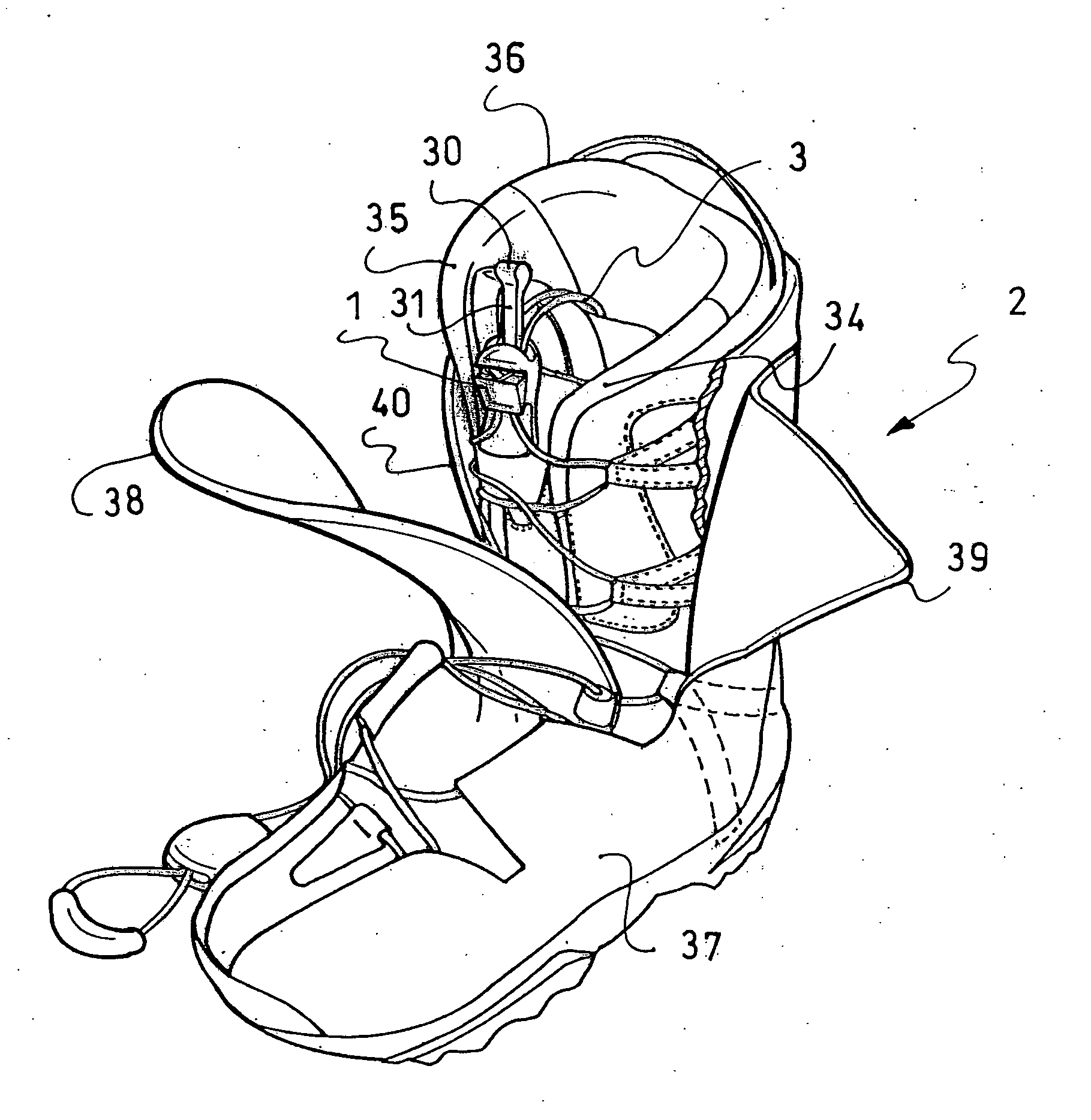
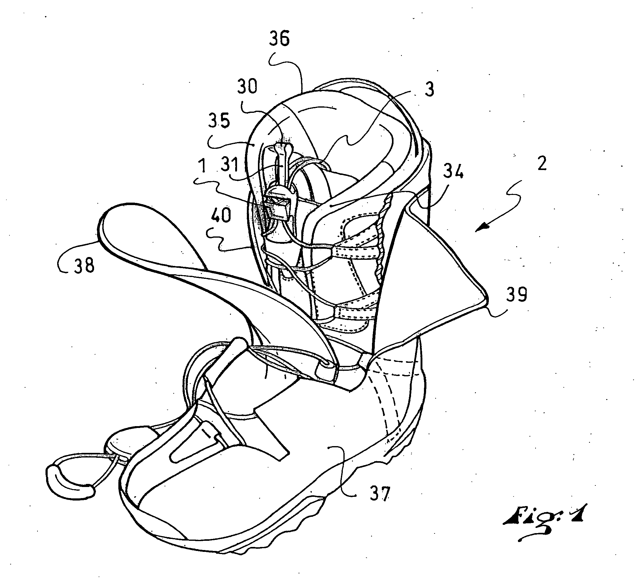
[0034] A first embodiment according to the invention will be described with reference to FIGS. 1-8.

[0035] A lace blocker 1 is shown in FIG. 1 for blocking a lace 3 for an application to a snowboard boot 2.

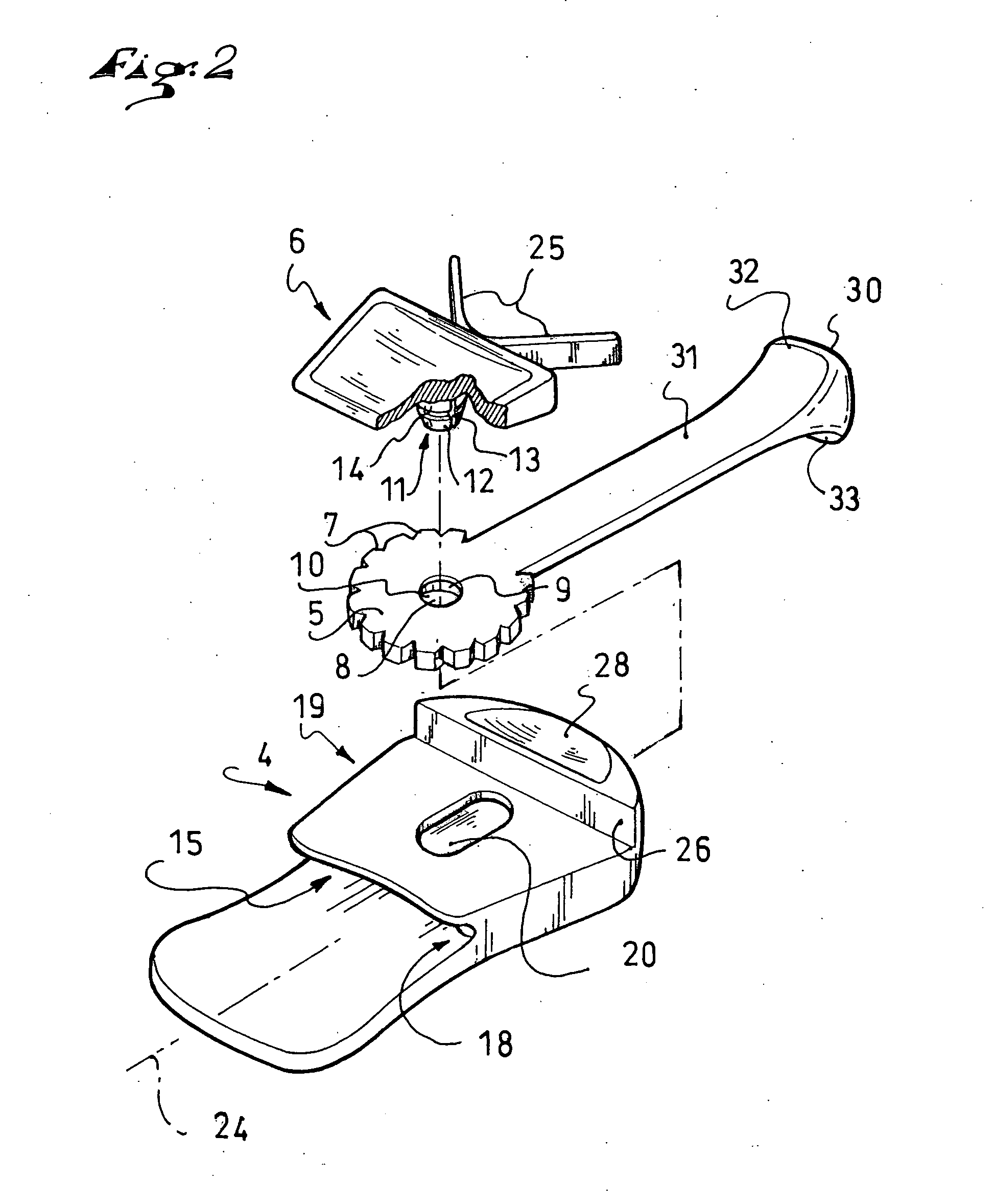
[0036] As shown more particularly in FIG. 2, the blocker 1, or blocking device, includes three elements, namely, a body 4, a blocking member 5 having a circular shape, and a cursor 6 located outside of the body 4 and connected to the blocking member 5 in order to manipulate it. The cursor can also be referred to as a slider or a pusher member.

[0037] In the detail shown in the drawings, the blocking member 5 can take the form of a wheel provided with teeth 7 on its periphery.

[0038] Through the center of the blocking member 5, or wheel, is a hole 8 which, in the illustrated example, is lined with a facing 9 to define an eyelet 10 for receiving an axle 11 of the cursor 6 in a force-fit, or snap fitting used in ratchets, which then provides the rotational axis of the wheel of the bl...

second embodiment

[0078] The second embodiment is shown in FIG. 9.

[0079] According to this embodiment, a blocker 50 has a hollow body 51, a blocking member shown in the form of a wheel 52, and a cursor 53. These elements are assembled to function in a manner similar to the blocker of the first embodiment.

[0080] According to the invention, an unblocking member has a gripping portion located at a distance from the hollow body 51.

[0081] The gripping portion is shown in the form of a grip 60 that is connected to a handle 61. In this manner, the unblocking member includes the grip 60 and the handle 61.

[0082] A connecting end of the handle 61, opposite the end receiving the grip, has a through hole 62. In this manner, the handle 61 and the wheel 52 are rotationally mounted on the same axle 63 originating from the cursor 53. Consequently, a traction on the grip 60 in a spacing direction with respect to the hollow body 51 biases the wheel 52 in an unblocking direction. Here again, the bias is direct, sinc...

third embodiment

[0083] the invention is shown in FIG. 10.

[0084] According to this example, a blocker has a wheel 70.

[0085] According to the invention, an unblocking member has a gripping portion located at a distance from the hollow body.

[0086] The gripping portion has a grip 80 that is connected to a handle 81. Here again, the unblocking member includes the grip 80 and the handle 81. The wheel 70, the grip 80 and the handle 81 form a unitary element.

[0087] In the third embodiment, the grip 80 includes an opening 82. This opening can be sufficiently large for the passage of a finger, allowing for a gripping with a bent finger.


PUM


Abstract

A device for blocking at least one strand of a lace or other filiform element, the device including a rotatable blocking member and a hollow body, the hollow body having a cavity for housing the blocking member. The blocking member is circular, freely rotatable, and elastically biased in the direction of blocking the strand(s). The device further includes an unblocking member. The unblocking member has a gripping portion located at a distance from the hollow body.

Description

CROSS-REFERENCE TO RELATED APPLICATION [0001] This application is based upon French Patent Application No. 03.08445, filed Jul. 10, 2003, the disclosure of which is hereby incorporated by reference thereto in its entirety and the priority of which is hereby claimed under 35 U.S.C. §119. BACKGROUND OF THE INVENTION [0002] 1. Field of the Invention [0003] The invention relates to a mechanical device for blocking flexible strands, such as cables, ropes, strings, laces, or any other such product. [0004] The invention relates more particularly to the blocking of laces for shoes, boots, and other articles of footwear. [0005] The invention further relates more particularly to the field of sports, specifically footwear for snowboarding, downhill skiing, cross-country skiing, bicycling, walking, hiking, and other activities. [0006] 2. Description of Background and Relevant Information [0007] It is known to block flexible strands, particularly the laces of articles of footwear, by means of a ...

Claims


Application Information

Patent Timeline
Patent Type & Authority Applications(United States)
IPC IPC(8): A43C7/00F16G11/10
CPCA43C7/00F16G11/10Y10T24/3716Y10T24/3976Y10T24/3713Y10T24/37F16G11/106
Inventor BORSOI, BRUNO
Owner SALOMON SA
Why Eureka
Try Eureka