Method for preparing three-dimensional signs

a three-dimensional and channel letter technology, applied in the field of channel letter manufacturing, can solve the problems of increasing considerable expense, laborious hand-held steps, and the need for all the necessary equipment, and achieve the effect of extending the capability and facilitating the subsequent bending and shaping of the return

Inactive Publication Date: 2005-01-13
LINENBERGER RANDOLPH M
View PDF10 Cites 22 Cited by
  • Summary
  • Abstract
  • Description
  • Claims
  • Application Information

AI Technical Summary

Benefits of technology

[0012] The present invention provides a method for forming all major components of a channel letter, i.e., the back, front and returns, on a single piece of manufacturing equipment, i.e., a router table, from a single piece of sheet stock. Among other things, the invention provides a method for an automated router table or other X, Y, Z cutting device to prepare a return that is cut to length, contains markings clearly identifying the location, direction and shape of the bends, and has material removed from the return at appropriate places to facilitate the subsequent bending and shaping of the return without using a press break. The process can be performed on automated routing tables already present in many sign shops or in metal forming facilities that would like to extend their capability to produce channel letter signs.

Problems solved by technology

While these efforts at automation constituted improvements over the time consuming efforts of craftsmen in preparing the back, front, returns and trim cap for a channel letter, they also added considerable expense.
All of these steps were performed laboriously by hand.
However, these advantages were offset by the considerable expense required for of all the necessary equipment.
Unless the fully automated sign shop could sell more signs, the increased capacity may not equate to increased profits due to the significant capital cost.
For these reasons, smaller sign shops could not justify the expense of purchasing automated equipment, and they continued to utilize manual techniques in making channel letters.

Method used


Image

  • Method for preparing three-dimensional signs
  • Method for preparing three-dimensional signs
  • Method for preparing three-dimensional signs

Examples


Embodiment Construction

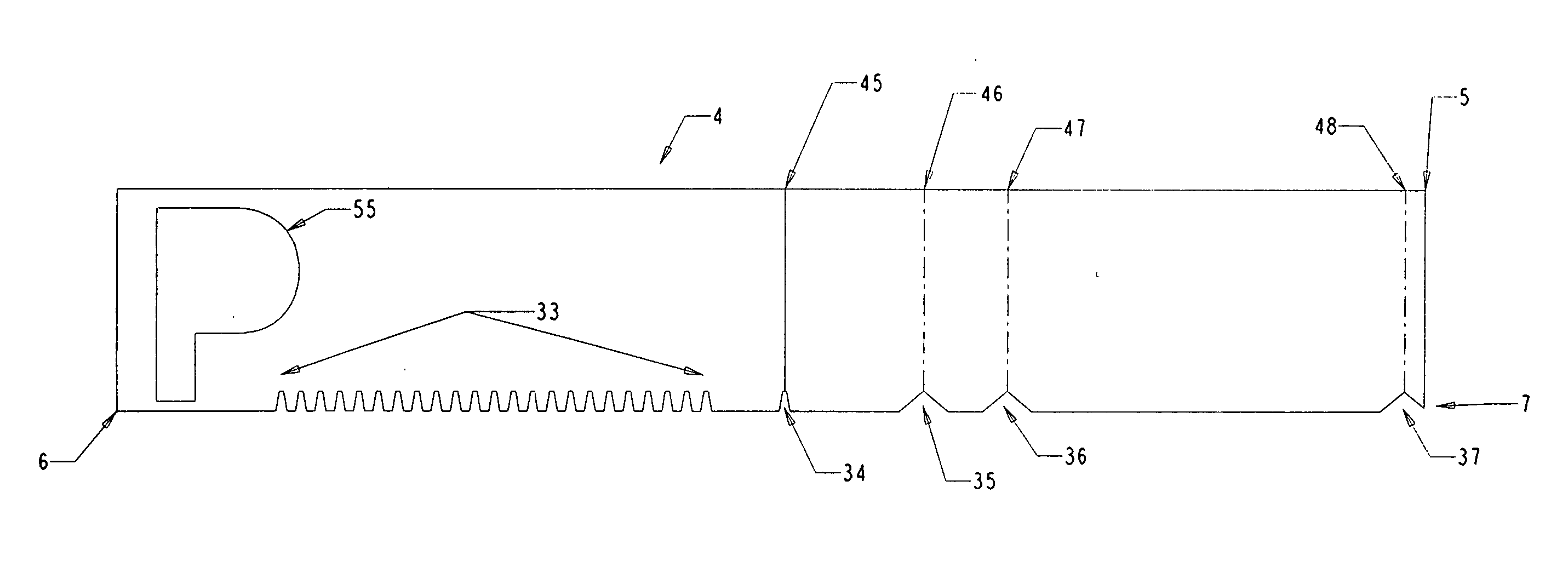
[0024] Among other things, the present invention includes a method of preparing a return, including a flange portion on one edge of the return, for subsequent shaping, bending and incorporation into a channel letter comprising cutting the outline of the return in the appropriate length and width from larger sheet stock, the outline including the removal of material from the flange portion of the return indicating where the return is to be shaped and bent, the material being removed in amounts facilitating the shaping and bending depending on the direction and amount of the shape or bend. The width of the return is scored to indicate the location and direction where the return is to be bent in an inward direction and sufficient material is removed from the return to facilitate the subsequent bending of the return in that direction. In addition the width of the return is scored to indicate the location and direction where the return is to be bent in an outward direction and sufficient...


PUM

PropertyMeasurementUnit
depthaaaaaaaaaa
depthaaaaaaaaaa
depthaaaaaaaaaa

Abstract

An improved method of preparing an intermediate for the return of a channel letter wherein the intermediate is cut from the same sheet stock as the back and face of the letter using a router, which removes material along the edge of the return and along the width of the return indicating the direction and shape that the finished return will take and removing material from the edge and width of the intermediate to facilitate the shaping and bending of the intermediate into its finished configuration.

Description

[0001] This application claims the benefit of provisional patent application Ser. No. 60 / 459,680, filed Mar. 31, 2003. This application also claims priority, as a continuation-in-part application, from U.S. patent application Ser. No. 09 / 844,954 filed Apr. 26, 2001, incorporated by reference herein, which claims priority from provisional patent application Ser. No. 60 / 199,933 filed Apr. 26, 2000.I. FIELD OF THE INVENTION [0002] The present invention is directed to the manufacture of channel letters. More specifically it relates to a method for more fully automating the manufacture of channel letters using a minimal amount of specialized equipment. It also includes the preparation of improved side walls, i.e., “returns,” for use in preparing such letters. II. BACKGROUND OF THE INVENTION [0003] Signs for outdoor advertising on stores, buildings and other applications are frequently prepared by making and mounting three-dimensional graphical elements, e.g., letters in any language, num...

Claims


Application Information

Patent Timeline
Patent Type & Authority Applications(United States)
IPC IPC(8): B21D11/08
CPCG09F13/0404B21D11/08Y10T83/0524
Inventor LINENBERGER, RANDOLPH M.
Owner LINENBERGER RANDOLPH M
Why Eureka
Try Eureka