

Extendible stent apparatus
- Summary
- Abstract
- Description
- Claims
- Application Information
AI Technical Summary
Benefits of technology
Problems solved by technology
Method used
Image

Examples
Embodiment Construction
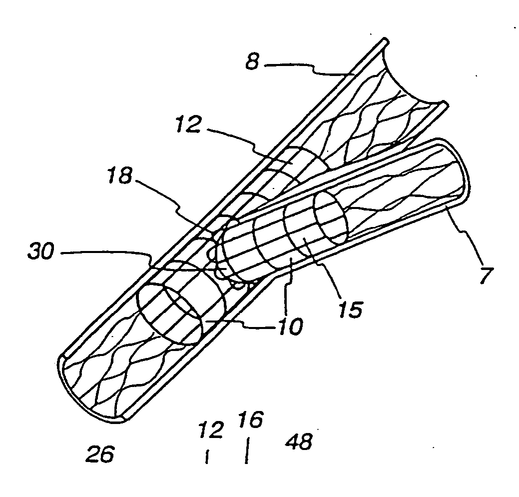
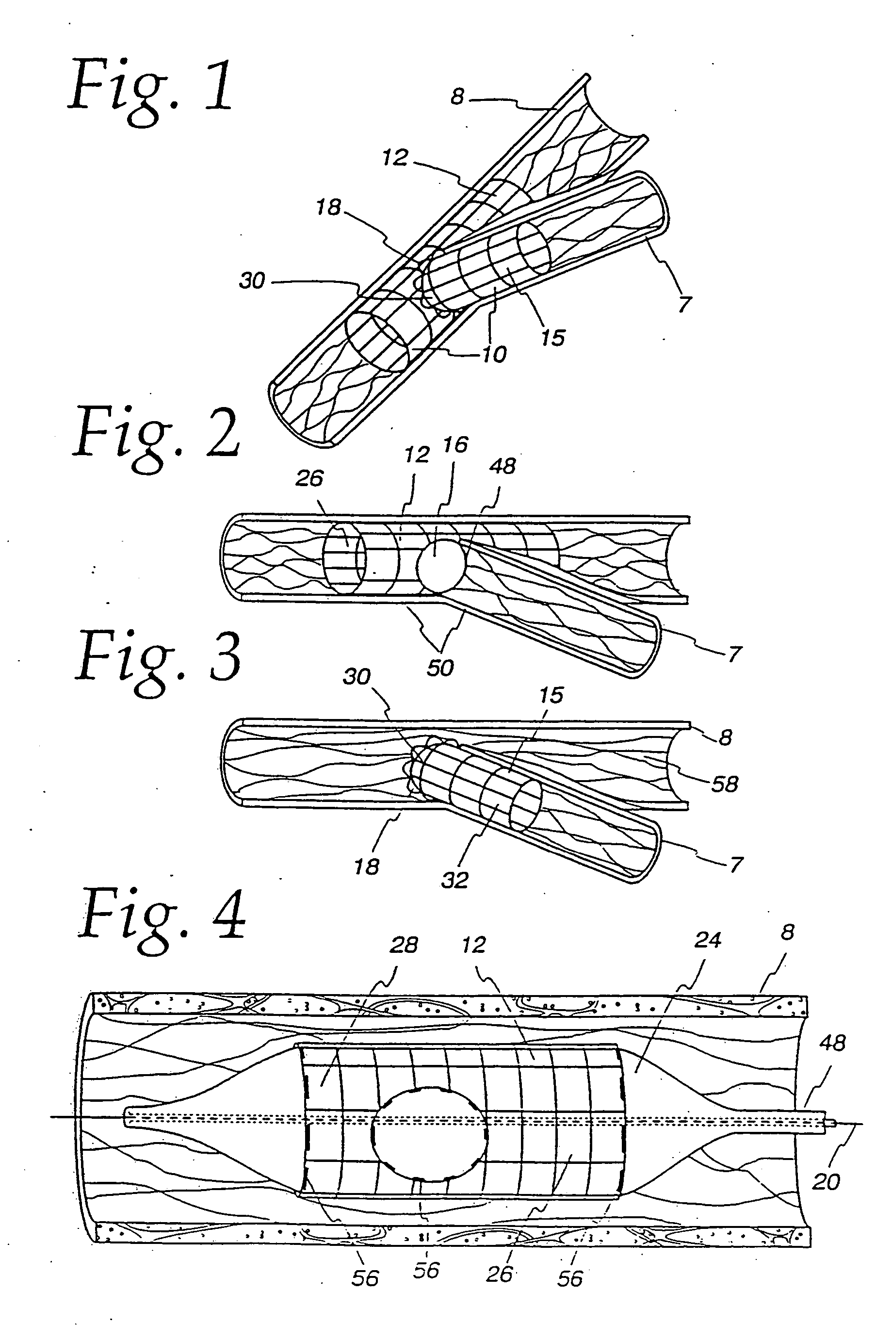
[0040] The bifurcating double-stent apparatus 10 of the present invention comprises a generally cylindrical main stent 12 and a generally cylindrical branch stent 15, which are shown as fully dilated in a subject main vessel 8 and a subject branch vessel 7, as illustrated in FIG. 1.
[0041] The main stent12 contains at least one generally circular side opening 16 located between the proximal end 26 and the distal end 28 of the main stent 12 (FIG. 2), which opening is positioned over and in registry with the opening 48 of a branch vessel in a vessel bifurcation 50, as shown in FIG. 2. The stent 12 and the side opening are imaged during imaging procedures either by constructing the stent of imageable materials or by placing markers 56 at appropriate locations, such as around the perimeter of the side opening 16 in the main stent 12, and at the proximal end 26 and distal end 28 of the main stent, as illustrated in FIG. 4.
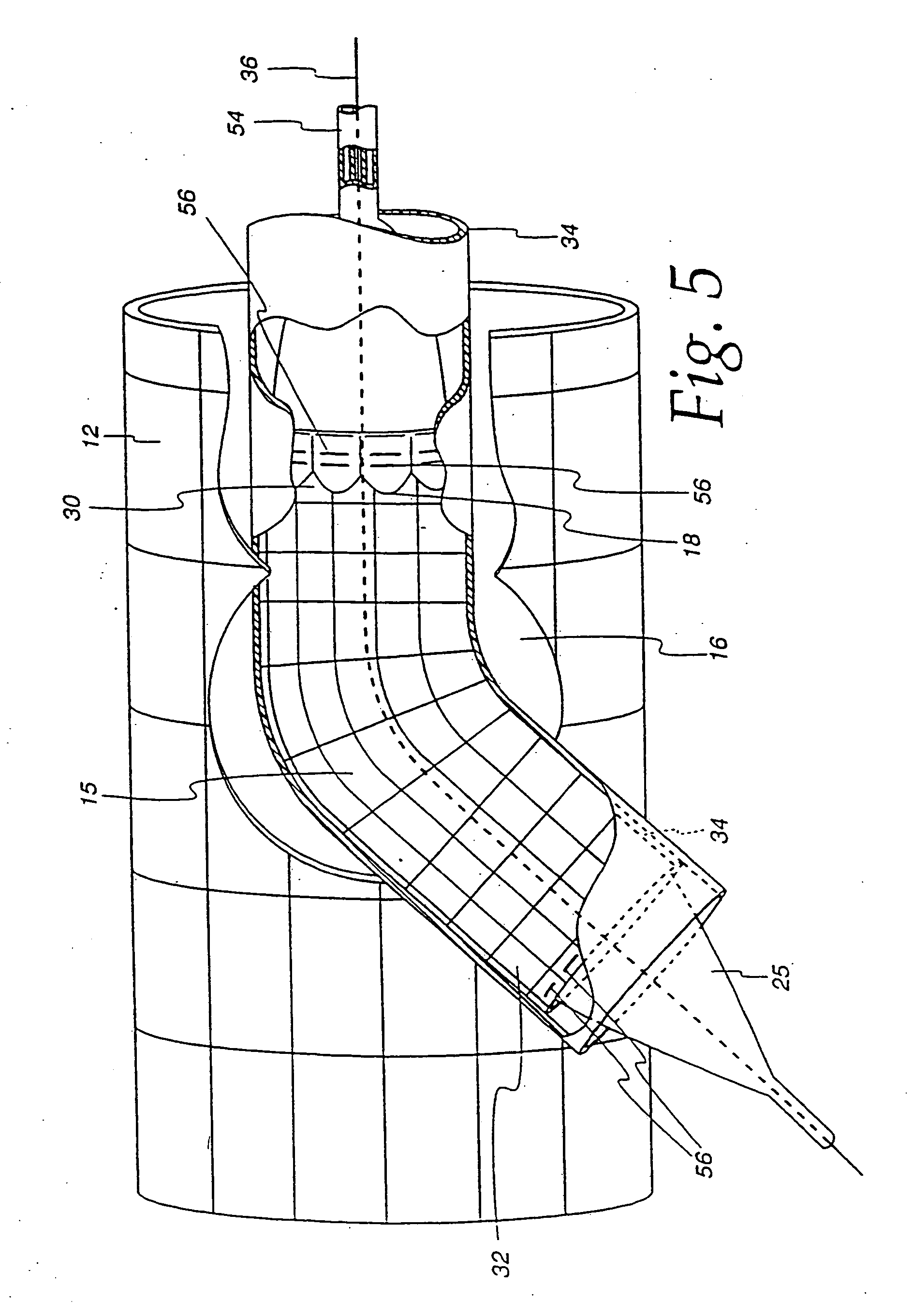
[0042] As shown in the embodiment of the invention illustrated in...
PUM
 Abstract
Description
Claims
Application Information