Collapsible batting cage

a batting cage and collapsible technology, applied in the field of collapsible batting cages, can solve the problems of inconvenient use of public batting cages for athletes, and inability to practice games 24 hours a day,

Inactive Publication Date: 2005-01-27
PETERSON KENNITH L
View PDF36 Cites 17 Cited by
  • Summary
  • Abstract
  • Description
  • Claims
  • Application Information

AI Technical Summary

Benefits of technology

[0007] In general terms, a collapsible batting cage is disclosed within which an athlete can practice pitching and batting a baseball without subjecting onlookers and property to the risk of injury or damage. The batting cage herein described in also suitable to enable other sports (e.g., golf, soccer, football, etc.) to be practiced within a safe environment for bystanders. The collapsible batting cage of this invention is particularly suitable for use in a residential area and includes a support frame that is adapted to be rotated between a collapsed position, when the batting cage is not in use, and a raised position, when the batting cage is to be used to practice one's game.
[0008] The support frame includes a plurality of (e.g., three) U-shaped frame members that are pivotally connected to a pair of side railings or a similar structure by means of hinge pins, whereby the support frame is rotatable relative to the side railings. The U-shaped frame members are linked together so as to be rotated in unison between the collapsed position so as to lie below the tops of the side railings and the raised position so as to stand upwardly above the side railings. The opposing pair of side railings cooperate with a front end railing and a back end railing to establish a confined practice area within which a baseball may be thrown and / or hit. A reversible winch is mounted on the front end railing, and a pull-up rail is slidable vertically along the back end railing.
[0009] A protective netting is tied to the U-shaped frame members of the support frame and to the pull-up rail so as to hang downwardly therefrom to cover the insides of the front end railing, the back end railing, and the opposing side railings. A cable which is connected to the winch at the front end railing is looped around the tops of each of the U-shaped frame members and then attached to the pull-up rail at the back end railing. When the reversible winch turns in a first direction, a pulling tension is generated in the cable to cause the support frame to be rotated to the raised position and the pull-up rail to slide upwardly, whereby the protective netting is correspondingly lifted above the front end, back end and side railings. However, when the winch turns in an opposite direction, the pulling tension in the cable is relaxed to allow the support frame to be rotated to the collapsed position and the pull-up rail to slide downwardly, whereby the netting is correspondingly lowered to a non-obtrusive, out of site location surrounded by the front end, back end, and side railings.

Problems solved by technology

However, it is an inconvenience for an athlete to have to frequently pack his gear and then travel to a distant site to improve his game.
Moreover, public batting cages are not available to the athlete on a 24 hour basis.
Similarly, the fees to use a public facility to practice one's games can become a cost problem, particularly when the athlete is young and must depend on his parents to cover his expenses.

Method used


Image

  • Collapsible batting cage
  • Collapsible batting cage
  • Collapsible batting cage

Examples


Embodiment Construction

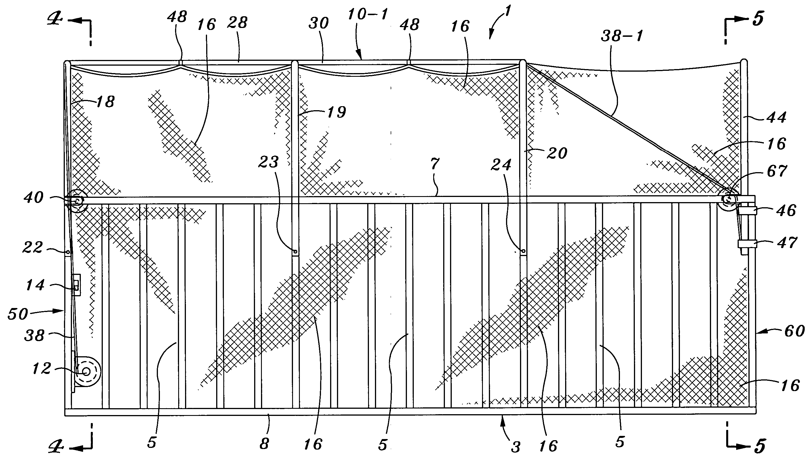
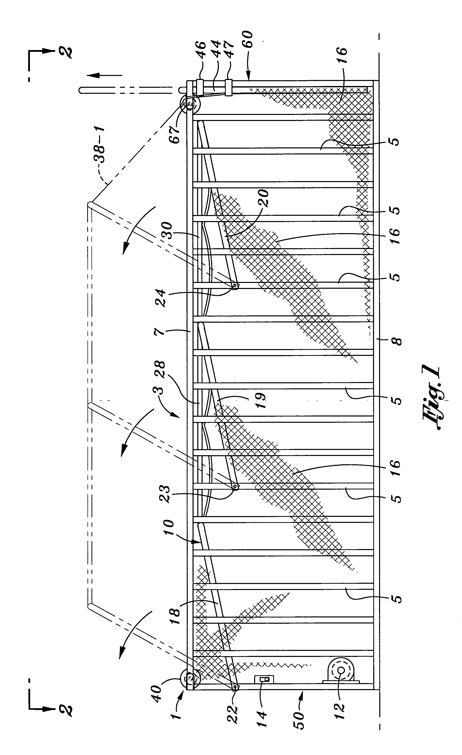
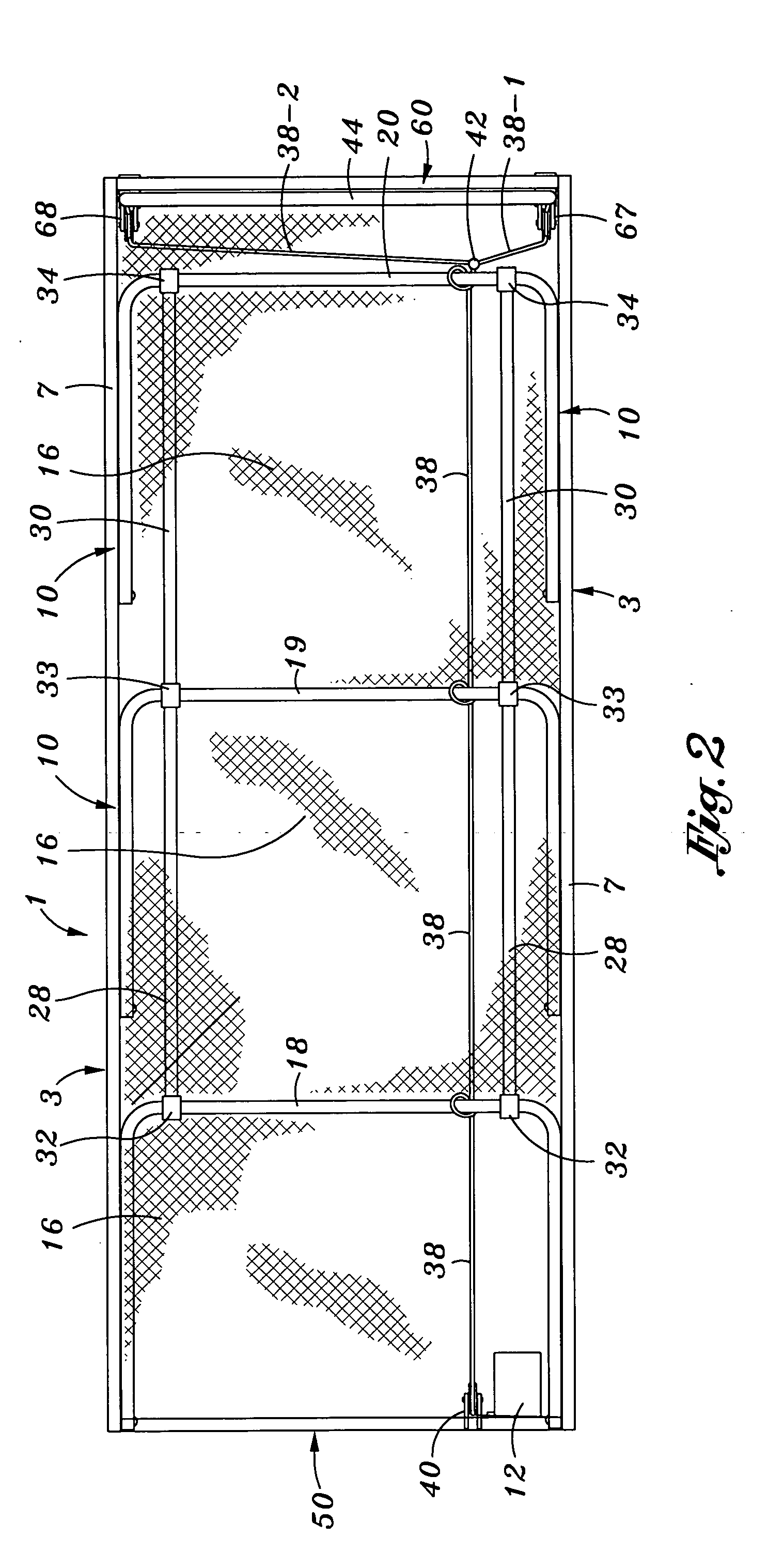
[0015] The collapsible batting cage 1 which forms the present invention is initially described while referring concurrently to FIGS. 1-3 of the drawings, where there is shown the batting cage 1 coupled to a pair of metal side railings 3 (best shown in FIG. 2) that are separated from one another to define the width of the practice area. Each side railing 3 has a series of spaced, parallel aligned rails 5 extending vertically between upper and lower support rails 7 and 8. However, it is to be understood that the collapsible batting cage 1 can also be used in conjunction with a pair of walls, fences, or similar structures, having a height of typically six feet or less so as to be able to comply with local ordinances in certain communities.

[0016] The collapsible batting cage 1 includes a support frame 10 that is pivotally coupled to the inside of the pair of side railings 3 and adapted to be rotated between a collapsed position (as shown in FIG. 1) at which time the batting cage is not...


PUM


Abstract

A collapsible batting cage having a support base (e.g., a front end, a back end and opposite sides) and a support frame to which a protective netting is attached. The support frame includes a plurality of U-shaped frame members that are pivotally connected to the support base so as to be rotatable relative thereto between a collapsed position, when the batting cage is not in use, to a raised position, when the batting cage is in use. A cable that is tied to the plurality of U-shaped frame members receives a pulling force from a winch for causing the U-shaped frame members to rotate from the collapsed position, where the protective netting is folded at an inconspicuous location within the support base, to the raised position, where the netting will hang above the support base. With the U-shaped frame members of the support frame rotated to the raised position and the netting hanging downwardly therefrom, the batting cage will provide a confined enclosure within which sports (e.g., baseball, golf, soccer, football, etc.) can be practiced without subjecting onlookers and property to the risk of injury or damage.

Description

BACKGROUND OF THE INVENTION [0001] 1. Field of the Invention [0002] This invention relates to a collapsible batting cage that is adapted to be quickly and easily rotated between a collapsed, folded position when the batting cage is not in use and a raised, upstanding position ready for use. The batting cage provides a confined enclosure within which sports (e.g., baseball, golf, soccer, football, etc.) can be practiced without subjecting onlookers and property to the risk of injury or damage. [0003] 2. Background Art [0004] Batting cages are available to the public at amusement parks and similar recreational facilities. However, it is an inconvenience for an athlete to have to frequently pack his gear and then travel to a distant site to improve his game. Moreover, public batting cages are not available to the athlete on a 24 hour basis. Similarly, the fees to use a public facility to practice one's games can become a cost problem, particularly when the athlete is young and must dep...

Claims


Application Information

Patent Timeline
Patent Type & Authority Applications(United States)
IPC IPC(8): A63B71/02
CPCY10S135/913A63B71/022
Inventor PETERSON, KENNITH L.
Owner PETERSON KENNITH L
Why Eureka
Try Eureka