Hydraulic system health indicator

a technology of health indicators and hydraulic systems, applied in hydrodynamic testing, instruments, mechanical equipment, etc., can solve problems such as damage to other components, and damage to components

Active Publication Date: 2005-02-03
CATERPILLAR INC
View PDF39 Cites 36 Cited by
  • Summary
  • Abstract
  • Description
  • Claims
  • Application Information

AI Technical Summary

Benefits of technology

According to another aspect of the invention, a method is provided for determining the operating health of a hydraulic system. The method may include the steps of determining a plurality of operating parameters of the hydraulic system during operation of the hydraulic system, and using the operating parameters to determine one or more working condition values of the system. Further, a first one of the one or more working condition values may be indicative of an effective bulk modulus value of an operating fluid within at least part of the hydraulic system.
According to yet another aspect of the invention, an apparatus is provided for determining the operating health of a hydraulic system. The apparatus may include a plurality of sensors operably connected to the hydraulic system and operable to indicate operating parameters of the hydraulic system during operation of the hydraulic system, and at least one processor operably connected in electrical communication with the sensors, the at least one processor being operable to determine one or more working condition values as a function of the actual operating parameters. Further, a first one of the one or more working condition values may be indicative of an effective bulk modulus value of an operating fluid within at least part of the hydraulic system.

Problems solved by technology

These hydraulic systems may include pumps and actuators, or the like, having moving parts and seals that may wear over time and that may eventually fail.
In addition to wear, such conditions as cavitation (e.g., the formation of cavities and their collapse within a hydraulic fluid of a hydraulic system) within a pump or another hydraulic component may harm the component or system or cause it to fail.
If the failure of a component is catastrophic, substantial debris may be introduced into the hydraulic system causing damage to other components.
If, however, an impending failure is predicted or sensed prior to catastrophic failure, a deteriorating component may be replaced or repaired before damage to other components is caused.
Moreover, if impending failure of a component is detected, maintenance on the component could be scheduled at the most opportune time to reduce the productivity losses typically caused by such a maintenance operation.
As the operating health of such a pump begins to deteriorate, for example by wear or cavitation within the system, operational inefficiencies may increase, system response may be slowed, and instability of the hydraulic system may result.
Without an appropriate method or apparatus for indicating or predicting such conditions as excessive wear or cavitation within a pump or other hydraulic component, impending failures may not be easily predicted, and thus the likelihood of catastrophic failures causing damage within a hydraulic system increases substantially.
Likewise, repairs may not be scheduled effectively to reduce losses of productivity during repair.
Similarly, increased leakage or cavitation within a system may lead to increased fuel consumption and decreased productivity, which conditions may not be otherwise detected.

Method used


Image

  • Hydraulic system health indicator
  • Hydraulic system health indicator
  • Hydraulic system health indicator

Examples


Embodiment Construction

Reference will now be made in detail to embodiments of the invention, examples of which are illustrated in the accompanying drawings. Wherever possible, the same or corresponding reference numbers will be used throughout the drawings to refer to the same or corresponding parts.

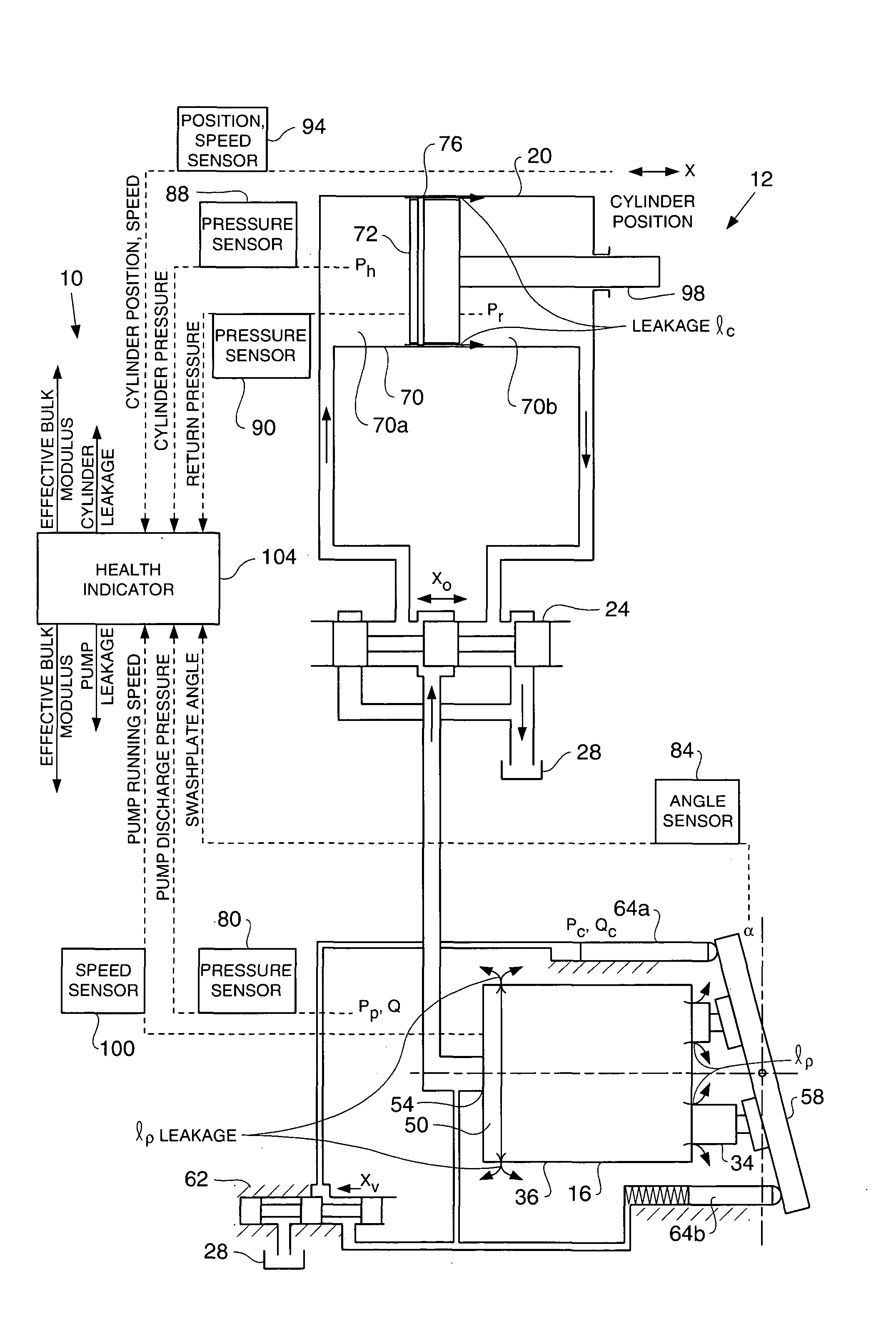
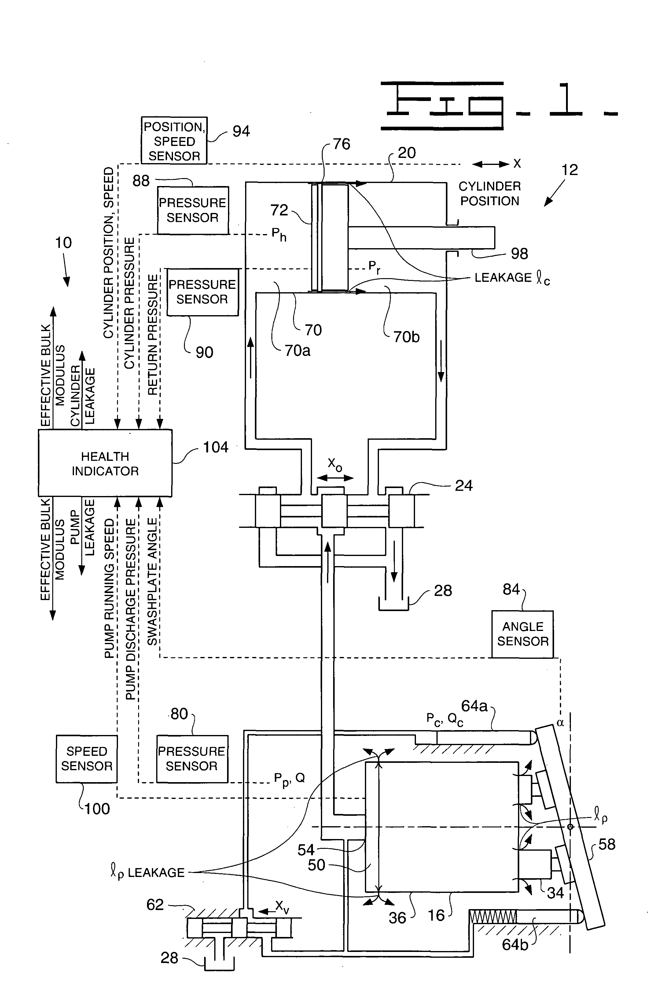
FIG. 1 shows an exemplary hydraulic system health indicator 10 operatively connected with an exemplary hydraulic system 12. The hydraulic system 12 of FIG. 1 includes a first fluid drive member 16, such as an axial piston type pump or motor, hydraulically connected with a second fluid drive member 20, such as a piston and cylinder arrangement. The first fluid drive member 16 (hereinafter referred to as pump 16) may supply pressurized fluid (P, Q) to the second fluid drive member 20 (hereinafter referred to as hydraulic actuator 20), for example through a valve 24, such as a four-way operating valve. The valve 24 may be disposed in hydraulic communication with a tank 28 so that the actuator 20 may receive ope...


PUM


Abstract

A method and apparatus for determining the operating health of a hydraulic system are provided. The method may include the steps of determining a plurality of operating parameters of the hydraulic system during operation of the hydraulic system, determining an estimated working condition value of the hydraulic system, modifying the estimated working condition value as a function of the operating parameters, and determining the operating health of the hydraulic system as a function of the working condition value. In one method, the working condition value may be indicative of an effective bulk modulus value of an operating fluid within at least part of the hydraulic system.

Description

TECHNICAL FIELD This invention relates generally to an apparatus and method for indicating a health condition of a hydraulic system, and more particularly to indicating a health condition of a hydraulic system, pump, actuator, or other hydraulic device. BACKGROUND Many work machines, such as earthworking machines or the like, include hydraulic systems and components for running motors and / or extending and retracting cylinders, for example. These hydraulic systems may include pumps and actuators, or the like, having moving parts and seals that may wear over time and that may eventually fail. In addition to wear, such conditions as cavitation (e.g., the formation of cavities and their collapse within a hydraulic fluid of a hydraulic system) within a pump or another hydraulic component may harm the component or system or cause it to fail. If the failure of a component is catastrophic, substantial debris may be introduced into the hydraulic system causing damage to other components. I...

Claims


Application Information

Patent Timeline
Patent Type & Authority Applications(United States)
IPC IPC(8): F15B19/00G01M99/00
CPCF15B19/005
Inventor DU, HONGLIU
Owner CATERPILLAR INC
Why Eureka
Try Eureka