Disk brake pad
a technology of brake pads and discs, applied in the direction of brake types, braking elements, friction linings, etc., can solve the problems of increasing the surface contact pressure of these end portions, increasing the noise reduction effectiveness reducing the noise reduction effect of the chamfered portion jb>10/b>, so as to inhibit uneven pad wear and promote long pad life.
- Summary
- Abstract
- Description
- Claims
- Application Information
AI Technical Summary
Benefits of technology
Problems solved by technology
Method used
Image
Examples
first embodiment
[0085] First Embodiment
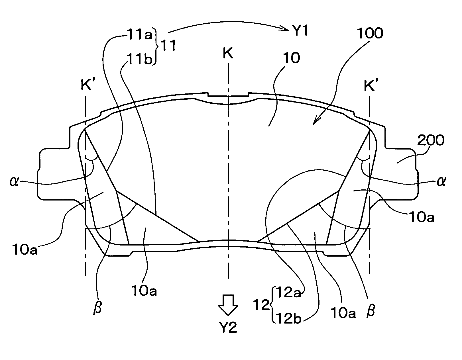
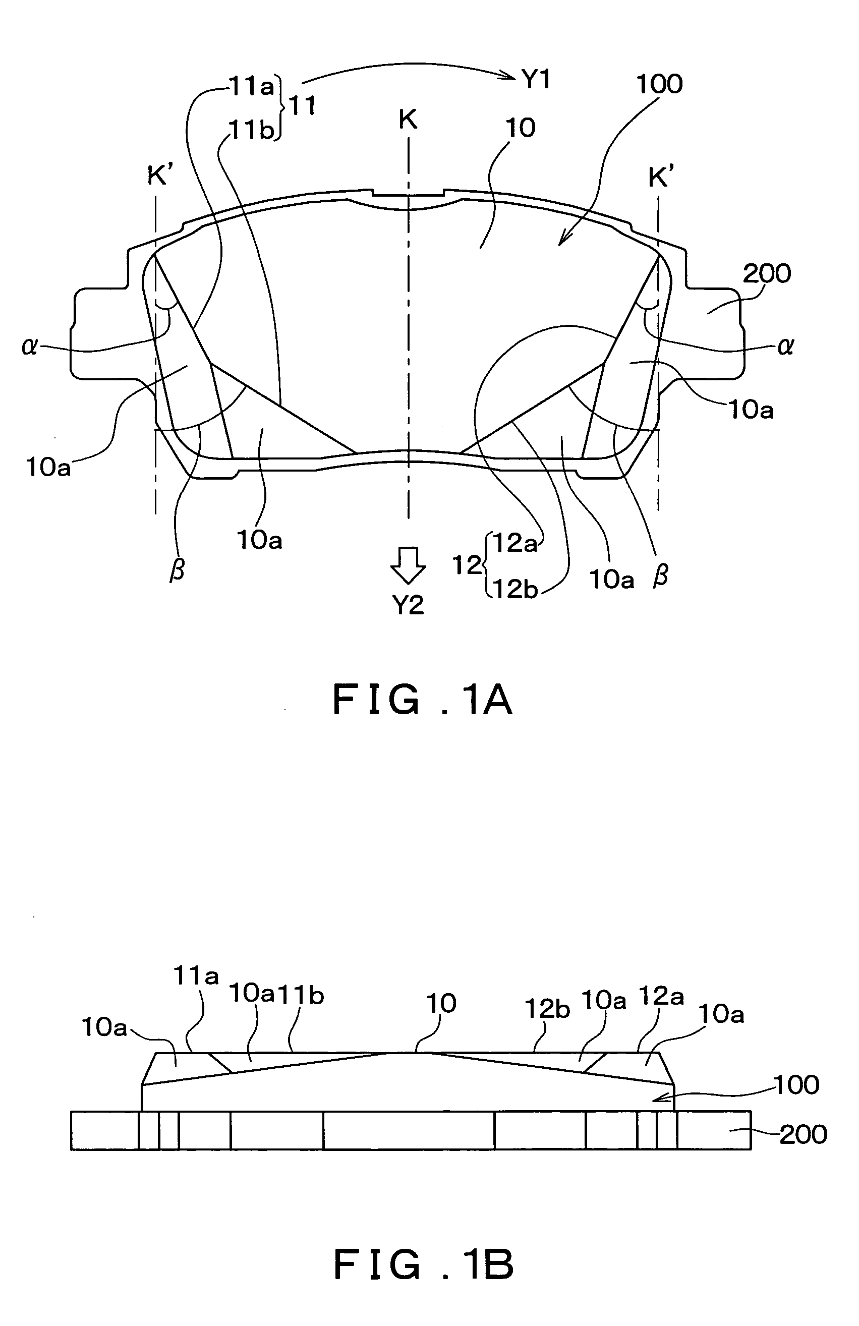
[0086]FIGS. 1A and 1B show the configuration of a disk brake pad 100 according to a first embodiment of the present invention. FIG. 1A shows a schematic plan view of the disk brake pad 100 as viewed from a front side of a friction surface 10 thereof, and FIG. 1B shows a side view of the disk brake pad 100 as viewed from the bottom of FIG. 1A.
[0087] The disk brake pad 100 according to the present invention controls rotation of a disk rotor 300 by using a cylinder 500 and a piston 400 to push the friction surface 10 against the disk rotor 300 while it rotates, in the same manner as described previously for FIG. 11.
[0088] As can be seen from FIG. 1, the disk brake pad 100 is integrally formed with a back plate (back metal) 200. Note that, the disk brake pad 100 is fixed to the back plate 200 at a back surface that is on the opposite side of the disk brake pad 100 to the friction surface 10.
[0089] Further, in a similar manner to above described FIG. 9A, the arr...
second embodiment
[0144] Second Embodiment
[0145] The second embodiment of the present invention is a modified form of the above described first embodiment. Accordingly, the following description will mainly focus on points of difference between the two embodiments.
[0146]FIGS. 5A and 5B show the configuration of a disk brake pad 100′ according to the second embodiment. FIG. 5A shows a schematic plan view of the disk brake pad 100′ when viewed from a front of the friction surface 10, and FIG. 5B shows a side view of the disk brake pad 100′ as viewed from the bottom of FIG. 2A.
[0147] The friction surface 10 of the disk brake pad 100′ is formed with a fan-shape. With this disk brake pad 100′, an external periphery portion of the fan-shaped friction surface 10 directly forms the portion of the friction surface 10 that is farther from the disk rotor rotation center. Further, an inner periphery portion of the fan-shaped friction surface 10 directly forms the portion of the friction surface 10 that is clos...
PUM
 Abstract
Description
Claims
Application Information
 - R&D
- Intellectual Property
- Life Sciences
- Materials
- Tech Scout
- Unparalleled Data Quality
- Higher Quality Content
- 60% Fewer Hallucinations
Browse by: Latest US Patents, China's latest patents, Technical Efficacy Thesaurus, Application Domain, Technology Topic, Popular Technical Reports.
© 2025 PatSnap. All rights reserved.Legal|Privacy policy|Modern Slavery Act Transparency Statement|Sitemap|About US| Contact US: help@patsnap.com


