This helps you quickly interpret patents by identifying the three key elements:
Problems solved by technology
Method used
Benefits of technology
Benefits of technology
Where the random luminance values are supplied to the ΔΣ modulator when the driving apparatus is started, the blinking of the display can be prevented.
Problems solved by technology
Therefore, the analog method has a disadvantage that a driving section is up-sized and the value of the driving current varies according to a temperature.
Method used
Image
Click on the blue label to locate the original text in one second.
Reading with bidirectional positioning of images and text.
Examples
first embodiment
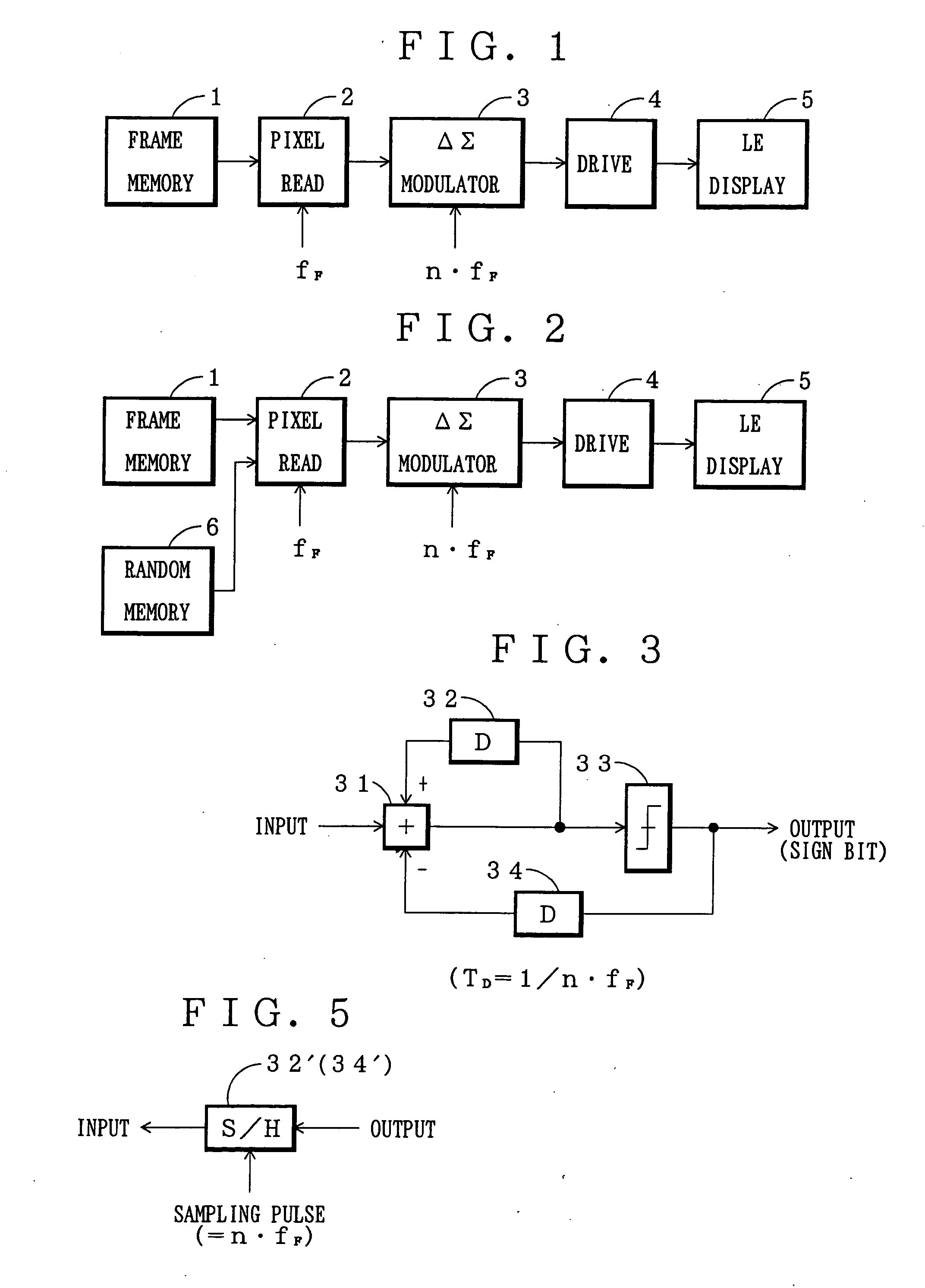
FIG. 3 is a block diagram of the ΔΣ modulator according to this invention.
In FIG. 3, reference numeral 31 denotes an addition unit; 32 and 34 denote a first and a second delay unit for delaying input pixel data by the time TDwhich is 1 / n of the frame period (1 / n·fF (fF is a frequency of the frame pulse); and 33 denotes a decision unit which produces a positive prescribed value if the output value from the addition unit 31 is a prescribed or larger value and produces a negative prescribed value if the output value is smaller than the prescribed value.
The first delay unit 32 delays the output from the addition unit 31. The addition unit 31 performs an addition of the delayed output and the input pixel data.
The output from the decision unit 33 is delayed by the second delay unit 34. The delayed output is subjected to subtraction by the addition unit 31.
The output to be supplied to the driving unit 4 produces a sign bit (if positive, “1”, and if negative, “0”) which represents th...
second embodiment
Now referring to FIG. 5, an explanation will be given of this invention.
In the first embodiment, the signal (pixel value) was delayed using the first delay unit 32 and the second delay unit 34, whereas in the second embodiment, these delay units is replaced by a sample-and-hold unit (S / H) 32′ (34′) as shown in FIG. 5.
The S / H unit 32′ holds and outputs an input value whenever a sampling pulse is received. Therefore, if the frequency of the sampling pulse is set at the frequency which is n-times of the frequency fF of the frame pulse, i.e. n·fF, the pixel data can be delayed like the first delay unit 32 and second delay unit 34.
third embodiment
Referring to FIGS. 5A and 5B, an explanation will be given of the
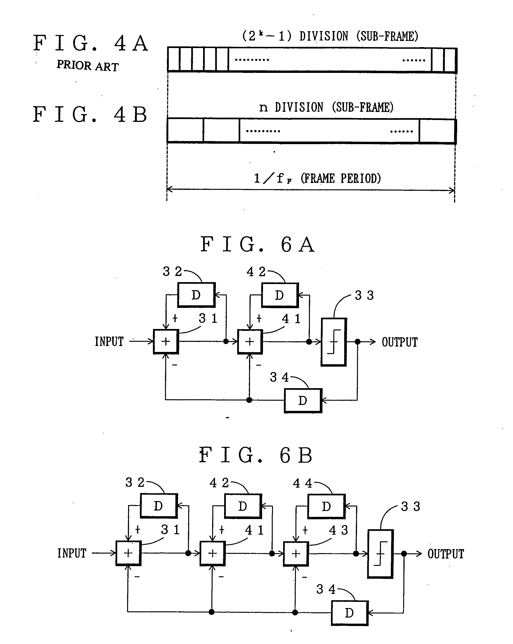
In the first embodiment, as shown in FIG. 3, the first-order ΔΣ modulator was used. In this embodiment, a second-order ΔΣ modulator as shown in FIG. 5A or a third-order modulator as shown in FIG. 5B is used.
As shown in FIG. 6A, the second-order ΔΣ modulator is constructed so that a second addition unit 41 and a third delay unit 42 are cascade-connected between the addition unit 31 and the decision unit 33 in the first-order ΔΣ modulator explained with reference to FIG. 1.
The second addition unit 41 makes the same operation as the addition unit 31. The delay time is set at the same time as that of the first delay unit 32 and the second delay unit 34.
As shown in FIG. 6B, the third-order ΔΣ modulator is constructed so that a third addition unit 43 and a fourth delay unit 44 are cascade-connected between the second addition unit 41 and the -decision unit 33 in the second-order ΔΣ modulator.
By raising the order of ...
PUM
Abstract
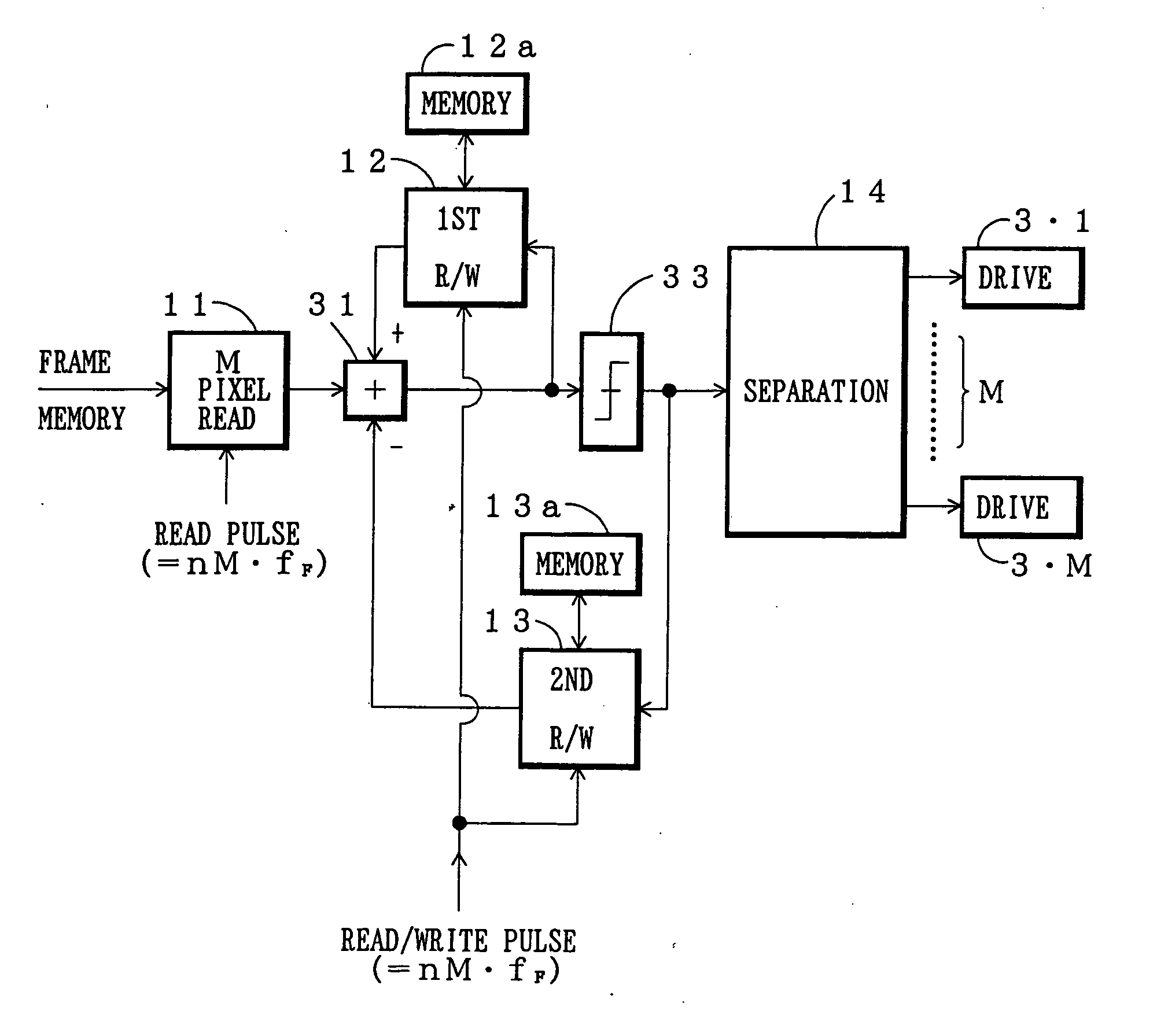
An apparatus for driving a light-emitting display controls the light-emission of light-emitting elements in such a manner that a driving current or driving voltage having a prescribed value to be supplied to the light-emitting elements is turned on or off by an on / off signal from a driving unit. The driving apparatus includes a pixel read section for reading the luminance values for the light-emitting elements in a frame period from an image signal and a ΔΣ modulator which operates in a sub-frame period which is 1 / n of the frame period according to the luminance values read by the pixel read section. The output of “1” or “0” from ΔΣ modulator is served as the on / off signal. The driving apparatus can further includes a random data generator for providing random luminance values for the individual pixels. In an image displaying operation, the output from the random data generator is directly supplied to the ΔΣ modulator in place of the output from the pixel read section, or otherwise added to the output from the pixel read section. This configuration provides an image with good quality and naturalness in the luminance by the driving at low speed.
Description
BACKGROUND OF THE INVENTION 1. Field of the Invention This invention relates to an apparatus for driving a light-emitting display constructed of light-emitting elements such as organic EL elements and light-emitting diodes. 2. Description of the Related Art Where an image is displayed on the light-emitting display, each light-emitting element must be illuminated with the luminance corresponding to the luminance value of each of pixels of an image signal. The technique for illuminating each light-emitting element with the luminance corresponding to the luminance value of the pixel includes an analog method and a time-divisional method. The analog method is to vary the driving current of illuminating the light-emitting element according to the luminance value. The time-divisional method is to turn on / off the driving current, which is maintained constant, according to the luminance value, thereby varying its “ON” time. The analog method requires linearity at high accuracy in ord...
Claims
Application Information
Patent Timeline
Application Date:The date an application was filed.
Publication Date:The date a patent or application was officially published.
First Publication Date:The earliest publication date of a patent with the same application number.
Issue Date:Publication date of the patent grant document.
PCT Entry Date:The Entry date of PCT National Phase.
Estimated Expiry Date:The statutory expiry date of a patent right according to the Patent Law, and it is the longest term of protection that the patent right can achieve without the termination of the patent right due to other reasons(Term extension factor has been taken into account ).
Invalid Date:Actual expiry date is based on effective date or publication date of legal transaction data of invalid patent.

