Vehicular lamp having a removable lens with an extension reflector

a technology of reflector and lens, which is applied in the direction of fixed installation, application, lighting and heating apparatus, etc., can solve the problems of not being able to remove the lens from the lamp body, and not being able to replace the entire lamp body, so as to avoid increasing the number of parts and degrading the aesthetic appearance of the lamp

Inactive Publication Date: 2005-02-03
KOITO MFG CO LTD
View PDF8 Cites 36 Cited by
  • Summary
  • Abstract
  • Description
  • Claims
  • Application Information

AI Technical Summary

Benefits of technology

[0009] An object of the present invention is to provide a lamp having a removable lens with an extensio

Problems solved by technology

With such techniques, however, it is not possible to remove the lens from the lamp body.
Thus, when the lens is damaged, it is not possible to replace only the lens, and accordingly replacing the entire lamp is required.
In particular, replacing a lamp, such as a headlamp, provided with a reflector and an aiming mechanism as a whole creates rising costs.
Further, it is not easy to demount the lens from the lamp body, and, as a result, this is obstacle to recycling components or parts.
Further, s

Method used


Image

  • Vehicular lamp having a removable lens with an extension reflector
  • Vehicular lamp having a removable lens with an extension reflector
  • Vehicular lamp having a removable lens with an extension reflector

Examples


third embodiment

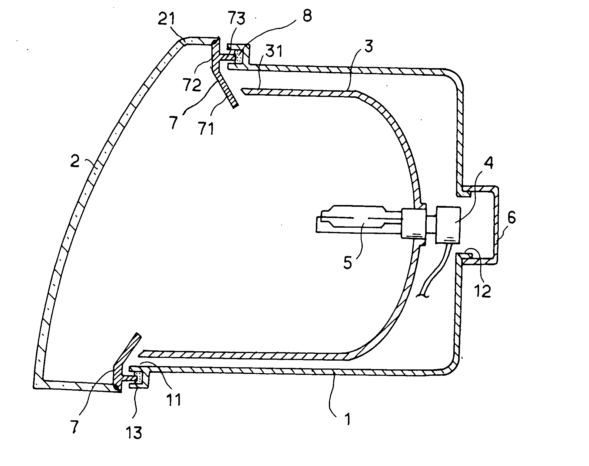
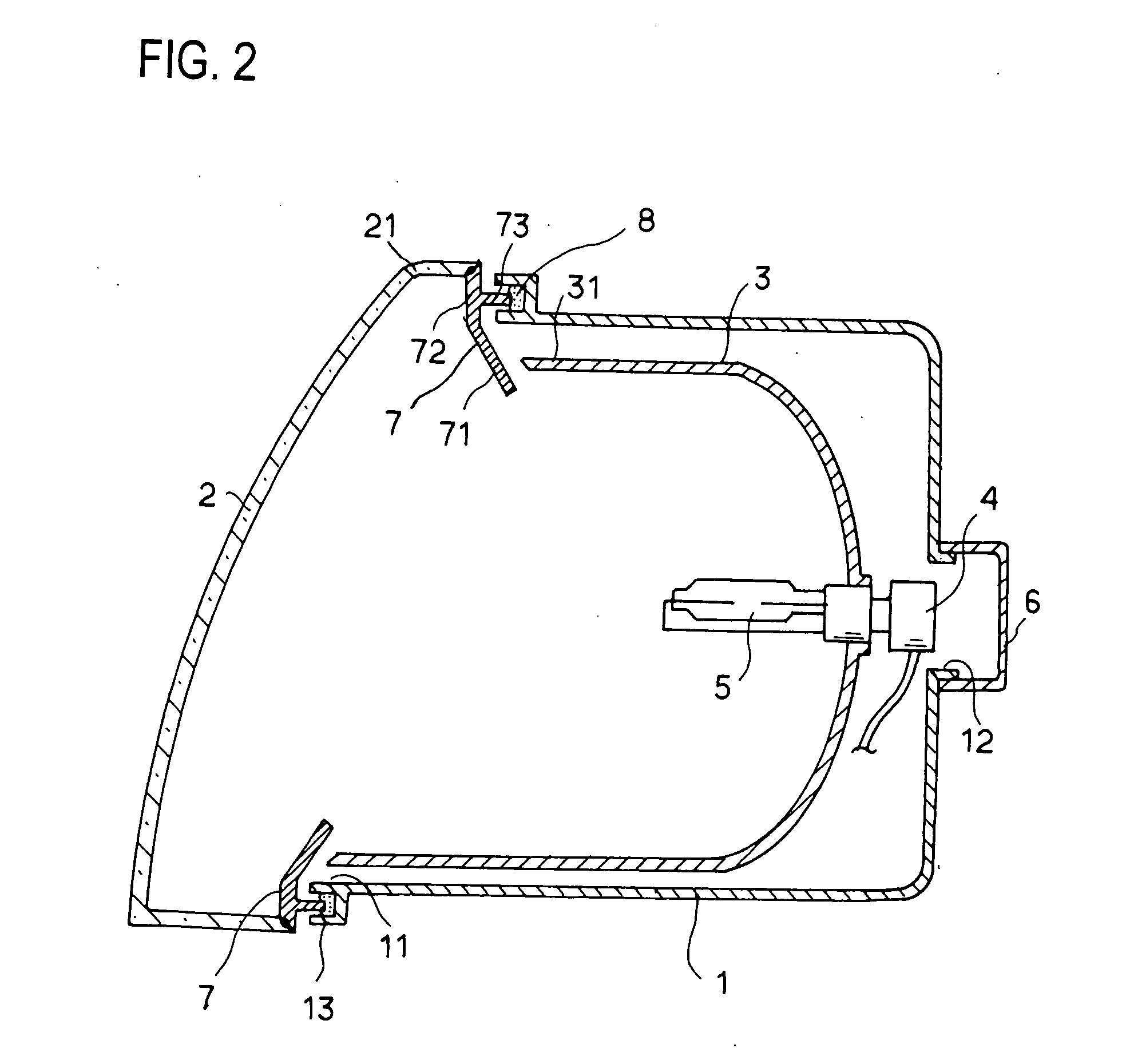
[0034]FIG. 7 is a cross-sectional view of the lamp according to another embodiment of the present invention, and illustrates modification of a portion of the aforementioned embodiment. The same as, or equivalent to, that of the third embodiment is denoted with the same reference numeral, and an explanation thereof will be omitted here.

[0035] The outer frame portion 72 of the extension reflector 7A is formed in the triangular shape in cross section, and the apex of an edge of the extension reflector 7A is attached to the external edge portion 21 of the lens 2 with welding X. Further, the seal groove 75 is configured in the back surface of the outer frame portion 72. A plurality of engagement holes 76 that are pierced in a thickness direction are provided at positions in a circumferential direction on an external periphery wall of the seal groove 75, i.e., an external periphery wall of the outer frame portion 72 of the extension reflector 7A. Moreover, in accordance therewith, the edg...

second embodiment

[0036] According to this embodiment, as with the second embodiment, for lens replacement, the lens 2 together with the extension reflector 7 can be easily removed from the lamp body 1 in a manner of pulling out the leg portion 15 from the seal groove 75 after releasing the hooks 74 from the engagement holes because the foam gasket 8A does not have adhesion. By way of this, lens replacement is made possible. Further, cost reduction can be promoted without any increase in number of parts, and recycling is effectively facilitated. Furthermore, the lens 2 is welded to the extension reflector 7A. Thus, just an contact area necessary for welding strength may by required on the lens. Thus, it is possible to improve the appearance of the headlamp HL when the lamp is viewed from the front. In this case, tips of the hooks 16 are configured not to protrude beyond the external periphery wall of the extension reflector 7A. This can avoid degrading the appearance of the headlamp HL based on expos...


PUM


Abstract

A vehicular headlamp includes a lamp body having an opening, a first reflector disposed within the lamp body, a lens, and a second reflector. The second reflector serves as an extension reflector to cover a gap between the opening of the lamp body and the first reflector. The lens and the second reflector are joined together at an edge portion thereof by laser welding. The second reflector has a leg portion on a back surface thereof. An edge portion of the opening has a groove to receive the leg portion, and seal material having a predetermined adhesibility, which can be pulled off, is injected into the groove. The second reflector joined to the lens is mounted on an edge of the opening of the lamp body via the seal material.

Description

BACKGROUND OF INVENTION [0001] 1. Field of the Invention [0002] The present invention relates to a vehicular lamp provided with an extension reflector in a lamp body thereof, which is configured such that a lens can be removed from the lamp body without degrading the aesthetic appearance of the vehicular lamp. [0003] 2. Background Art [0004] A vehicular lamp, such as a headlamp for a vehicle, is typically configured to dispose a bulb and a reflector as a light source within a lamp chamber, which is formed by mounting a lens on a front opening portion of a lamp body. For the configuration that the lens is mounted on the front opening portion of the lamp body, a technique that the lens is integrated with the lamp body in a manner of laser welding may be used. Alternatively, a bonding technique using seal material, such as a bonding agent, hot melt adhesive, or the like may be used. With such techniques, however, it is not possible to remove the lens from the lamp body. Thus, when the ...

Claims


Application Information

Patent Timeline
IPC IPC(8): F21S8/10B29C65/16B29C65/42B29C65/58B29C65/72F21V7/00F21V17/00F21V31/04
CPCB29C65/1635B29C65/4815B29C65/58B29C65/72B29K2023/12B29K2067/00B29K2067/006B29K2069/00B29L2031/747B60Q2900/20F21S48/1208F21S48/1311F21S48/25F21V31/04Y02T10/88B29C66/542B29C66/543B29C66/112B29C66/114B29C66/1162B29C66/12449B29C66/12461B29C65/42B29C66/71B29C66/8322F21S41/29F21S41/395F21S43/50B29K2067/003
Inventor OTANI, HARUOSUGIYAMA, FUJIHIKOYAMAZAKI, KAZUHIROSUZUKI, MICHIHIKO
Owner KOITO MFG CO LTD
Why Eureka
Try Eureka