Video projector

a projector and projector technology, applied in the field of video projectors, can solve the problems and achieve the effect of lowering the aesthetic appearance of the projector

Active Publication Date: 2010-06-10
SANYO ELECTRIC CO LTD
View PDF6 Cites 3 Cited by
  • Summary
  • Abstract
  • Description
  • Claims
  • Application Information

AI Technical Summary

Benefits of technology

[0005]The security slot, strap passage, and security bar are distinct on the exterior surface of the projector even when the antitheft cable is not fastened to the projector. This lowers the aesthetic appearance of the projector.

Problems solved by technology

This lowers the aesthetic appearance of the projector.

Method used


Image

  • Video projector
  • Video projector
  • Video projector

Examples


Embodiment Construction

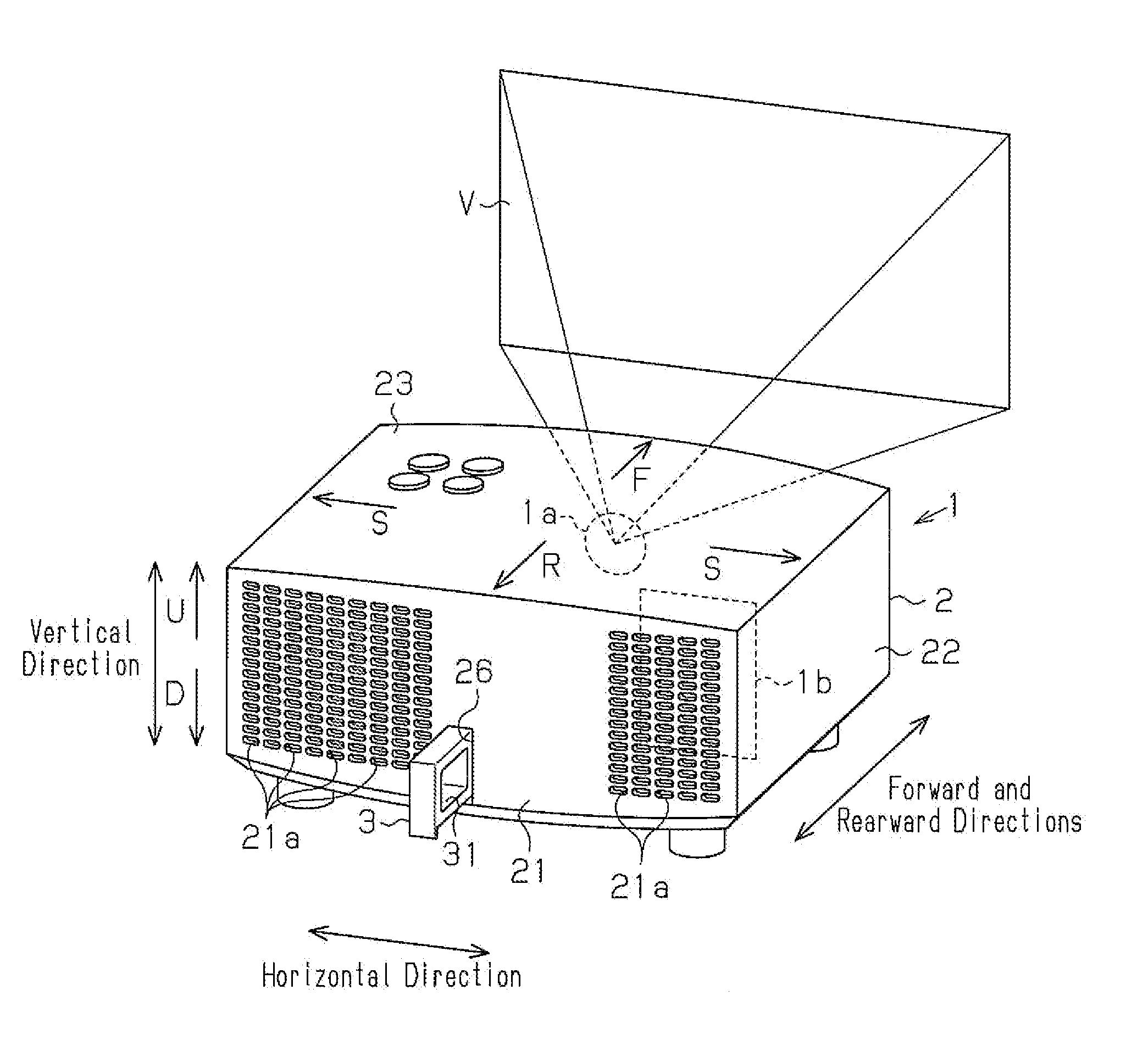
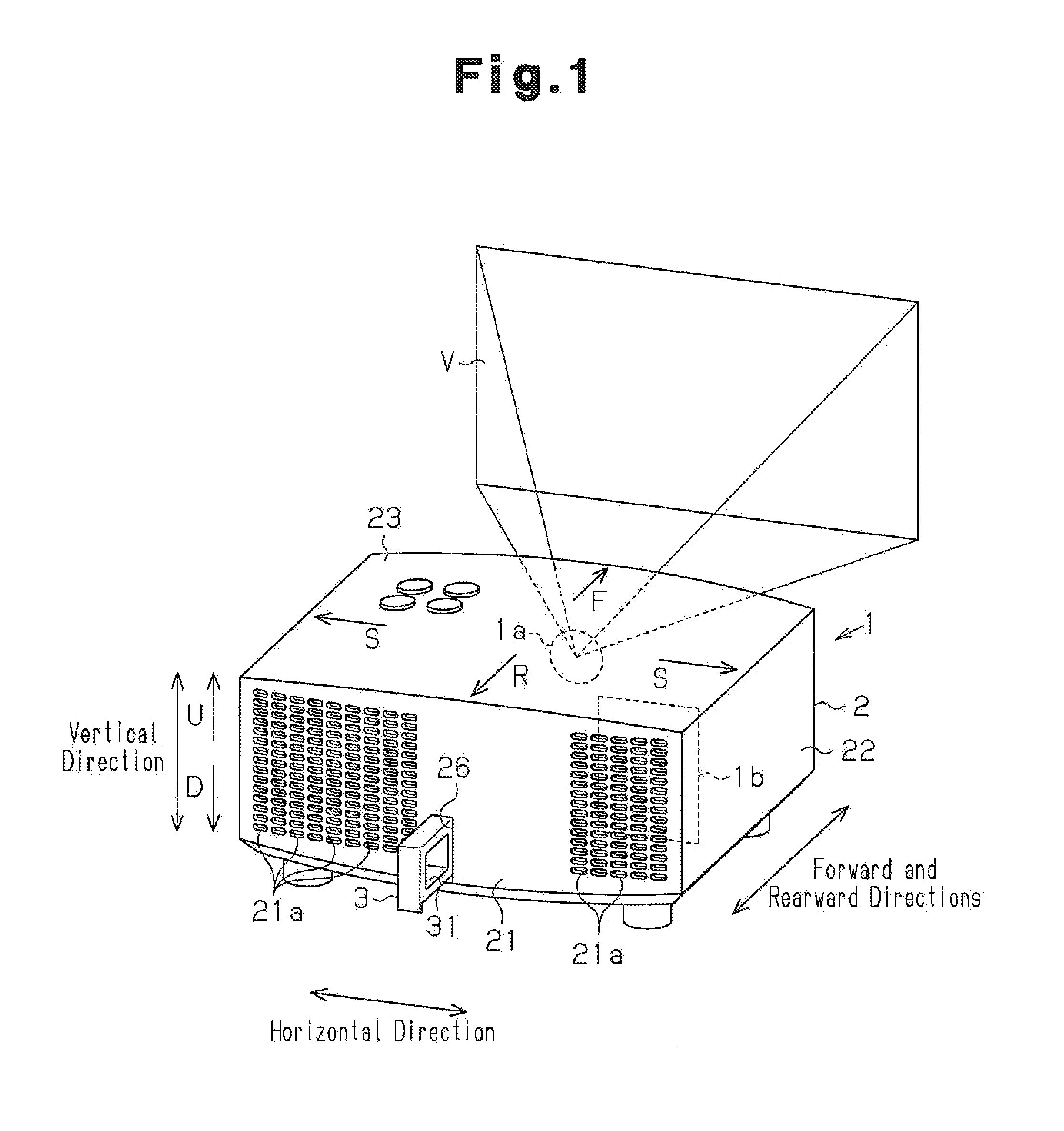
[0018]A video projector according to one embodiment of the present invention will now be discussed. The video projector is, for example, a liquid crystal display (LCD) projector that uses an LCD panel as a light bulb through which light is transmitted to generate a picture.

[0019]FIG. 1 shows an LCD projector 1 including a housing 2. The housing 2 accommodates various components for projecting and displaying a picture V. The components include, for example, optical components (not shown), such as a light source and an LCD panel, and electronic components (not shown), which control the LCD projector 1. In the drawings, arrows F, R, S, U, and D respectively indicate forward, rearward, sideward, upward, and downward directions of the housing 2. The housing 2 may be formed from resin. The housing 2 may include a rigid frame such as a metallic chassis.

[0020]The LCD projector 1 is a front projector. The LCD projector 1 has a front surface in which a projection lens 1a is arranged. The LCD ...


PUM


Abstract

A video projector including a housing which accommodates a component for projecting and displaying a picture. A cable insertion member is fastenable to an antitheft cable. The cable insertion member is retractable into the housing.

Description

CROSS-REFERENCE TO RELATED APPLICATIONS[0001]This application is based upon and claims the benefit of priority from prior Japanese Patent Application No. 2008-309753, filed on Dec. 4, 2008, the entire contents of which are incorporated herein by reference.BACKGROUND OF THE INVENTION[0002]The present invention relates to a video projector that is fastenable to an antitheft cable or cable.[0003]A portable projector includes an antitheft structure, which is fastened to an antitheft cable to prevent theft. One example of such an antitheft structure is a Kensington lock, which is used to secure a projector to an immovable object, such as a table (for example, refer to Japanese Laid-Open Patent Publication No. 2008-20551). The antitheft structure includes a lock shaft arranged on the distal end of an antitheft cable. In a state in which the basal end of the antitheft cable is secured to an immovable object, the lock shaft is inserted into a security slot of the projector. The lock shaft i...

Claims


Application Information

Patent Timeline
Patent Type & Authority Applications(United States)
IPC IPC(8): H04N5/64G03B21/16
CPCH04N9/3141G03B21/00G03B21/005
Inventor YUYAMA, KEIJIYOSHIMURA, TAICHIHIROUCHI, YASUYUKI
Owner SANYO ELECTRIC CO LTD
Why Eureka
Try Eureka